Road marking device

A road marking and car body technology, applied in the field of road construction equipment, can solve problems such as intermittent markings, affecting road maintenance effects, and non-straight markings, and achieve the effect of improving mobility

Inactive Publication Date: 2018-09-07
合肥银创宏达机器人有限公司
View PDF12 Cites 4 Cited by
  • Summary
  • Abstract
  • Description
  • Claims
  • Application Information

AI Technical Summary

Problems solved by technology

During the maintenance process of the road surface, it is often necessary to repair the road surface, resulting in intermittent and incoherent markings on the road
However, if mechanical marking is used to repair the road markings, it is not flexible enough to make a fuss
Using manual line drawing is often prone to non-straight lines, which affects the effect of road maintenance

Method used


Image

  • Road marking device
  • Road marking device
  • Road marking device

Examples


Embodiment 1

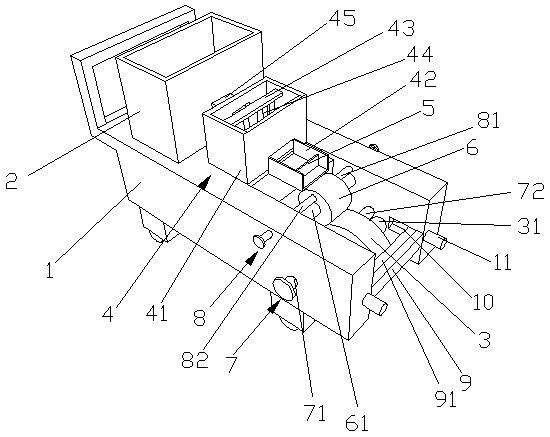
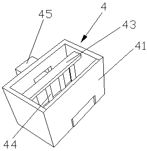
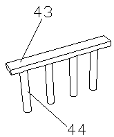
[0023] Such as Figure 1-3 As shown, a road marking device of the present invention includes a car body 1, one end of the car body 1 is provided with a material box 2, the other end of the car body 1 is a U-shaped opening structure, and the U-shaped opening at the other end of the car body 1 A first roller 3 is movable in the opening, and a heating device 4 is also arranged on the car body 1 between the feed box 2 and the first roller 3. The heating device 4 includes a heating box 41 and a material guide box 42. One part of the heating box 41 The side wall is provided with a feeding pipe 45, and the heating box 41 is connected between the feeding pipe 45 and the material box 2, and the heating box 41 side wall on the opposite side of the feeding pipe 45 is provided with a material guide box 42, and the material guide box 42 One end of one end communicates with the heating box 41, and the other end of the material guide box 42 is also provided with a filter plate 5, the filter ...

Embodiment 2

[0025]One end of the car body 1 is provided with a material box 2, and the other end of the car body 1 is a U-shaped opening structure, and the first roller 3, the material box 2 and the first roller 3 are movable in the U-shaped opening at the other end of the car body 1. The car body 1 between is also provided with heating device 4, and heating device 4 comprises heating box 41 and feeder box 42, and the side wall of heating box 41 is provided with feeding pipe 45, and heating box 41 passes through feeding pipe. 45 is connected with the material box 2, and the heating box 41 side wall on the opposite side of the feed pipe 45 is provided with a material guide box 42, and one end of the material guide box 42 is connected with the heating box 41, and the other end of the material guide box 42 Also be provided with filter plate 5 inside, and filter plate 5 is grid-like structure, also be provided with the second roller 6 on the car body 1 of material guide box 42 other ends, the ...


PUM


Abstract

The invention provides a road marking device, and particularly relates to the technical field of road construction equipment. The road marking device comprises a vehicle body, wherein a material box is arranged at one end of the vehicle body; the other end of the vehicle body is of a U-shaped opening structure; a first roller is movably arranged in the U-shaped opening of the other end of the vehicle body; a heating device is arranged on the vehicle body between the material box and the first roller, and comprises a heating box and a material guide box; a material conveying pipe is arranged atone side wall of the heating box; a material guide box is arranged at the side wall of the heating box opposite to the material conveying pipe; a second roller is arranged on the vehicle body at theother end of the material guide box, and is movably arranged in the U-shaped opening of the other end of the vehicle body; a first adjusting rod and a second adjusting rod are also arranged in the U-shaped opening of the other end of the vehicle body; a scraping plate is arranged at the opening of the other end of the vehicle body. The road marking device has the advantages that the marking position can be conveniently adjusted, the fluidity of coating can be improved, the excessive coating stuck onto the first roller can be adjusted and scraped, and the like.

Description

technical field [0001] The invention relates to the technical field of road construction equipment, in particular to a road marking device. Background technique [0002] Road traffic markings are traffic safety facilities composed of various lines, arrows, characters, facade marks, raised road signs and contour marks marked on the road surface. The traffic markings drawn on the road can effectively guide the driver's sight and regulate the driving path of vehicles. Our country has a vast territory and long road mileage, and many road surfaces are seriously damaged. During the maintenance process of road pavement, it is often necessary to repair the pavement, resulting in intermittent and incoherent markings on the road. However, if mechanical marking is used to repair the road markings, it seems not flexible enough, making a fuss over a molehill. Using manual line drawing is often prone to non-straight lines, which affects the effect of road maintenance. Contents of the...

Claims


Application Information

Patent Timeline
Patent Type & Authority Applications(China)
IPC IPC(8): E01C23/20
CPCE01C23/203
Inventor 余爱玲
Owner 合肥银创宏达机器人有限公司
Why Eureka
Try Eureka