
Suction disc device and bottle preform conveying mechanism

A technology of suction cups and suction cup seats, which is applied in the direction of conveyors, conveyor objects, suction cups, etc., can solve the problems that the preform is difficult to ensure the adsorption movement, affects the production progress and efficiency, and the preform falls, etc., and achieves simple structure and improved Speed ​​and success rate, the effect of firm adsorption

Pending Publication Date: 2018-09-07
苏州誉阵自动化科技有限公司
View PDF0 Cites 0 Cited by
  • Summary
  • Abstract
  • Description
  • Claims
  • Application Information

AI Technical Summary

Problems solved by technology

[0002] At present, when the preform moves during the production process, it is necessary to extend the suction head to the bottom of the bottle for negative pressure adsorption, and then move to the target position. Because the bottom of the bottle is not all flat, some preforms have a convex bottom, and different bottles The raised angles of the bottom are also different, so when moving the preform, suction heads of different shapes are required to adapt to different bottle bottoms, and during the process of adsorption and movement, due to the matching degree of the suction head and the bottle bottom, the preform It is difficult to ensure that the preform is adsorbed and moved at the centered position. If the preform is not adsorbed at the centered position, the adsorbed preform is prone to fall during the moving process, which will affect the production progress and efficiency.

Method used


Image

  • Suction disc device and bottle preform conveying mechanism
  • Suction disc device and bottle preform conveying mechanism
  • Suction disc device and bottle preform conveying mechanism

Examples


no. 1 example

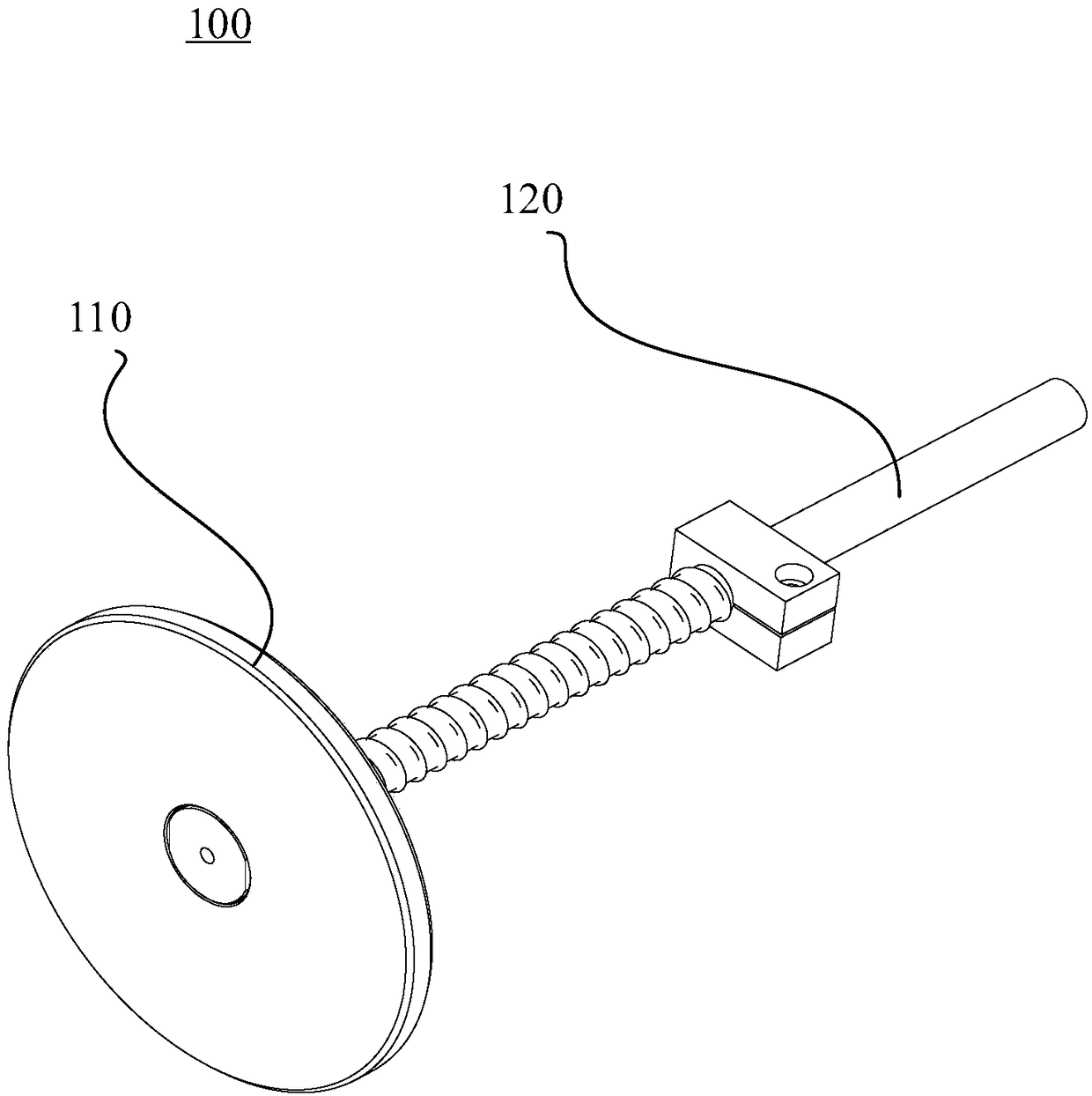
[0030] Please refer to figure 1 , the present embodiment provides a sucker device 100, which includes a sucker seat 110 and a connecting pipe 120, the suction surface of the sucker seat 110 is a plane, a through hole is arranged in the center of the sucker seat 110, the connecting pipe 120 is a hollow pipe, and the connecting pipe 120 One end communicates with the through hole.

[0031] It should be noted that, first, if figure 1 As shown, the center of the suction cup seat 110 is provided with a through hole, the connecting pipe 120 is a hollow pipe, one end of the connecting pipe 120 communicates with the through hole, the other end of the connecting pipe 120 is connected to an external suction mechanism, and the suction surface of the suction cup seat 110 contacts and fits The bottle mouth is closed after the surface of the bottle mouth, so that a closed space is formed in the bottle, and the external suction mechanism exhausts the air in the closed bottle through the conn...

no. 2 example

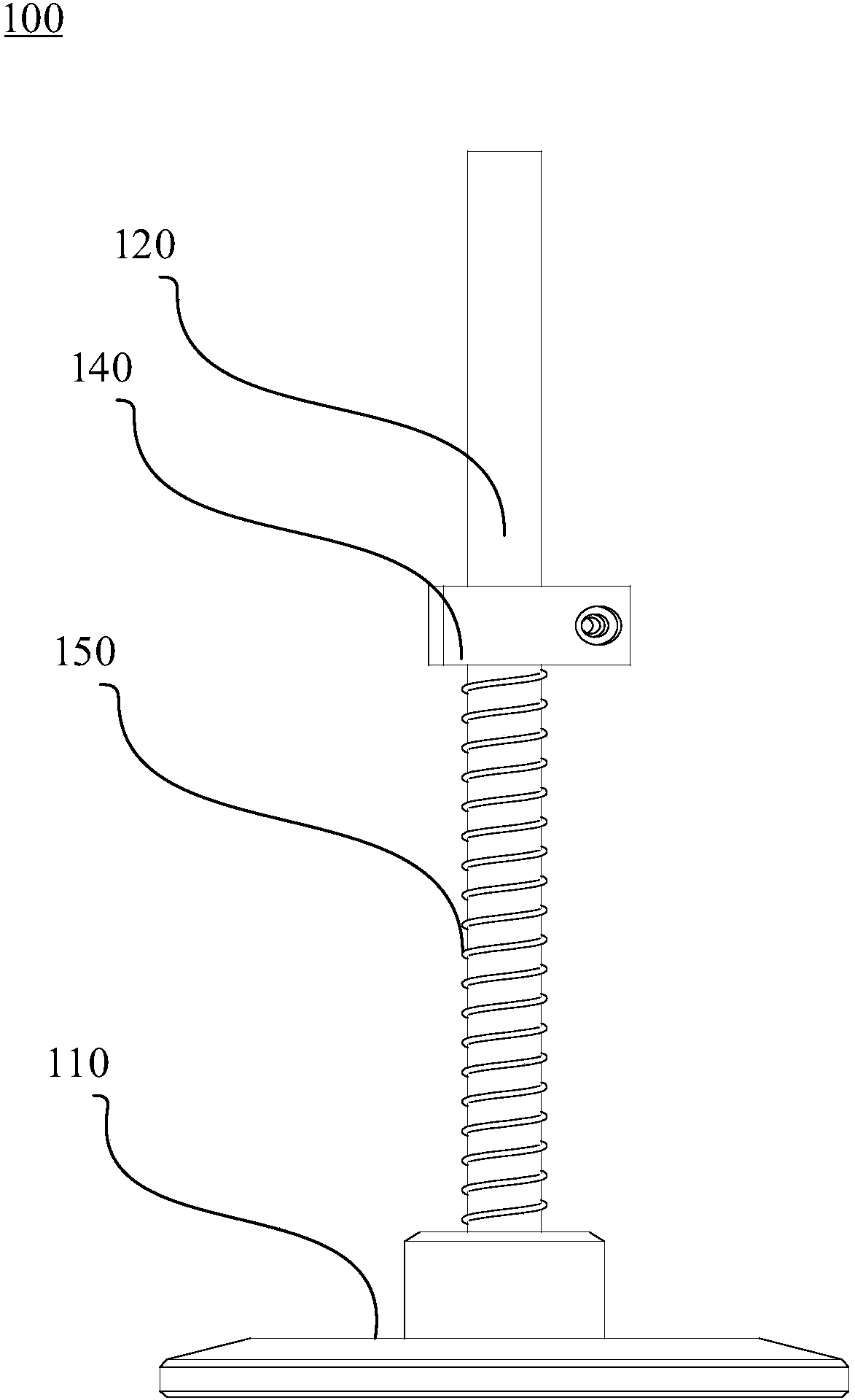
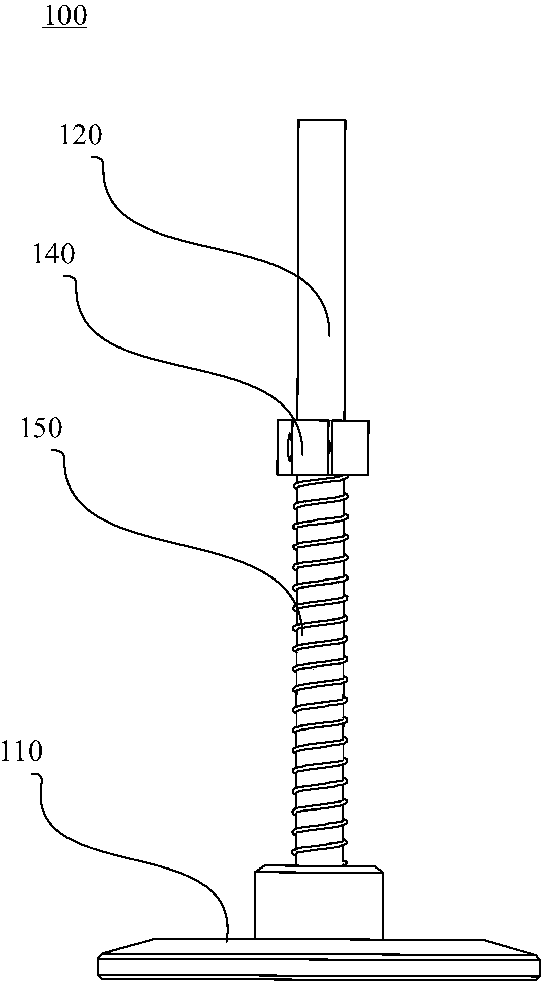
[0052] This embodiment provides a preform conveying mechanism including a suction mechanism, a lifting mechanism and any one of the above-mentioned suction cup devices 100, the suction cup device 100 is connected to the suction mechanism through a connecting pipe 120, and the suction cup device 100 is connected through a fixed block 140 and a lifting mechanism connect.

[0053] This embodiment provides a preform conveying mechanism. When the preform is adsorbed, the above-mentioned lifting mechanism moves the suction cup device 100 to the position above the preform through the fixed block 140 and then slowly descends, so that the suction surface of the suction cup seat 110 contacts and fits the bottle mouth. Close the mouth of the bottle after the surface, so that a closed space is formed in the bottle, and the other end of the connecting pipe 120 is connected to the above-mentioned suction mechanism. The air pressure inside the bottle is lower than the outside air pressure, a...


PUM


Abstract

The invention provides a suction disc device and a bottle preform conveying mechanism, and belongs to the field of bottle preform production. The suction disc device comprises a suction disc seat anda connection pipe, wherein the adsorption surface of the suction disc seat is a plane; a through hole is formed in the centre of the suction disc seat; the connection pipe is a hollow pipeline; and one end of the connection pipe is communicated with the through hole. According to the suction disc device provided by the invention, the speed of establishing a vacuum environment in a bottle is increased through designing a bottle opening adsorption structure and by virtue of the negative pressure adsorption principle of a suction disc, so that the adsorption efficiency is increased; and meanwhile, the suction disc device is adaptive to adsorption for bottle preforms with different dimensions and shapes, so that the adaptability of the suction disc is improved, and the adsorption surface can be much closely adsorbed onto the surface of a bottle opening, so that stable adsorption is achieved. The suction disc device and the bottle preform conveying mechanism are high in practicability and simple in structure.

Description

technical field [0001] The invention relates to the field of preform production, in particular to a suction cup device and a preform conveying mechanism. Background technique [0002] At present, when the preform moves during the production process, it is necessary to extend the suction head to the bottom of the bottle for negative pressure adsorption, and then move to the target position. Because the bottom of the bottle is not all flat, some preforms have a convex bottom, and different bottles The raised angles of the bottom are also different, so when moving the preform, suction heads of different shapes are required to adapt to different bottle bottoms, and during the process of adsorption and movement, due to the matching degree of the suction head and the bottle bottom, the preform It is difficult to ensure that the preform is adsorbed and moved at the centered position. If the preform is not adsorbed at the centered position, the adsorbed preform is prone to fall duri...

Claims


Application Information

Patent Timeline
IPC IPC(8): B65G47/91F16B47/00
CPCF16B47/00B65G47/912B65G2201/0244
Inventor 惠洁戴益灿崔祥
Owner 苏州誉阵自动化科技有限公司
Learn More