Medium-low-speed magnetic levitation train, walking part and lap joint structure used for improving redundancy

A technology for connecting structures and running parts, applied in vehicle parts, railway car body parts, motor vehicles, etc., can solve problems such as the impact of line operation, the inability of a single suspension frame unit to suspend, and the impact on the stable suspension of trains, so as to improve redundancy. Effect

Pending Publication Date: 2018-09-07
湖南轨道技术应用研究中心有限公司 +1
View PDF0 Cites 5 Cited by
  • Summary
  • Abstract
  • Description
  • Claims
  • Application Information

AI Technical Summary

Problems solved by technology

During the operation of the train, when any controller, sensor, or electromagnet in the suspension module fails, it will affect the stable suspension of the train, which may cause the corresponding single suspension frame unit of the train to fail to suspend, and directly fall on the track to cause collision and friction with the track. Towed by skids under the traction of other normal suspension units, these problems have occurred many times in the actual operation of medium and low-speed maglev trains, which have a great impact on line operation

Method used


Image

  • Medium-low-speed magnetic levitation train, walking part and lap joint structure used for improving redundancy
  • Medium-low-speed magnetic levitation train, walking part and lap joint structure used for improving redundancy
  • Medium-low-speed magnetic levitation train, walking part and lap joint structure used for improving redundancy

Examples


Embodiment Construction

[0030] The following will clearly and completely describe the technical solutions in the embodiments of the present invention with reference to the accompanying drawings in the embodiments of the present invention. Obviously, the described embodiments are only some, not all, embodiments of the present invention. Based on the embodiments of the present invention, all other embodiments obtained by persons of ordinary skill in the art without making creative efforts belong to the protection scope of the present invention.

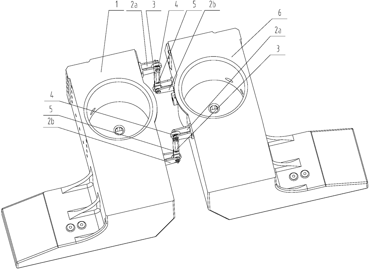
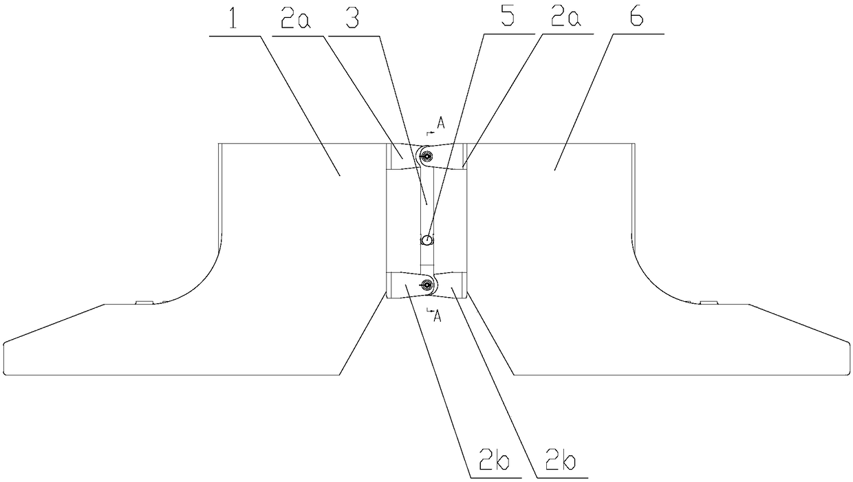
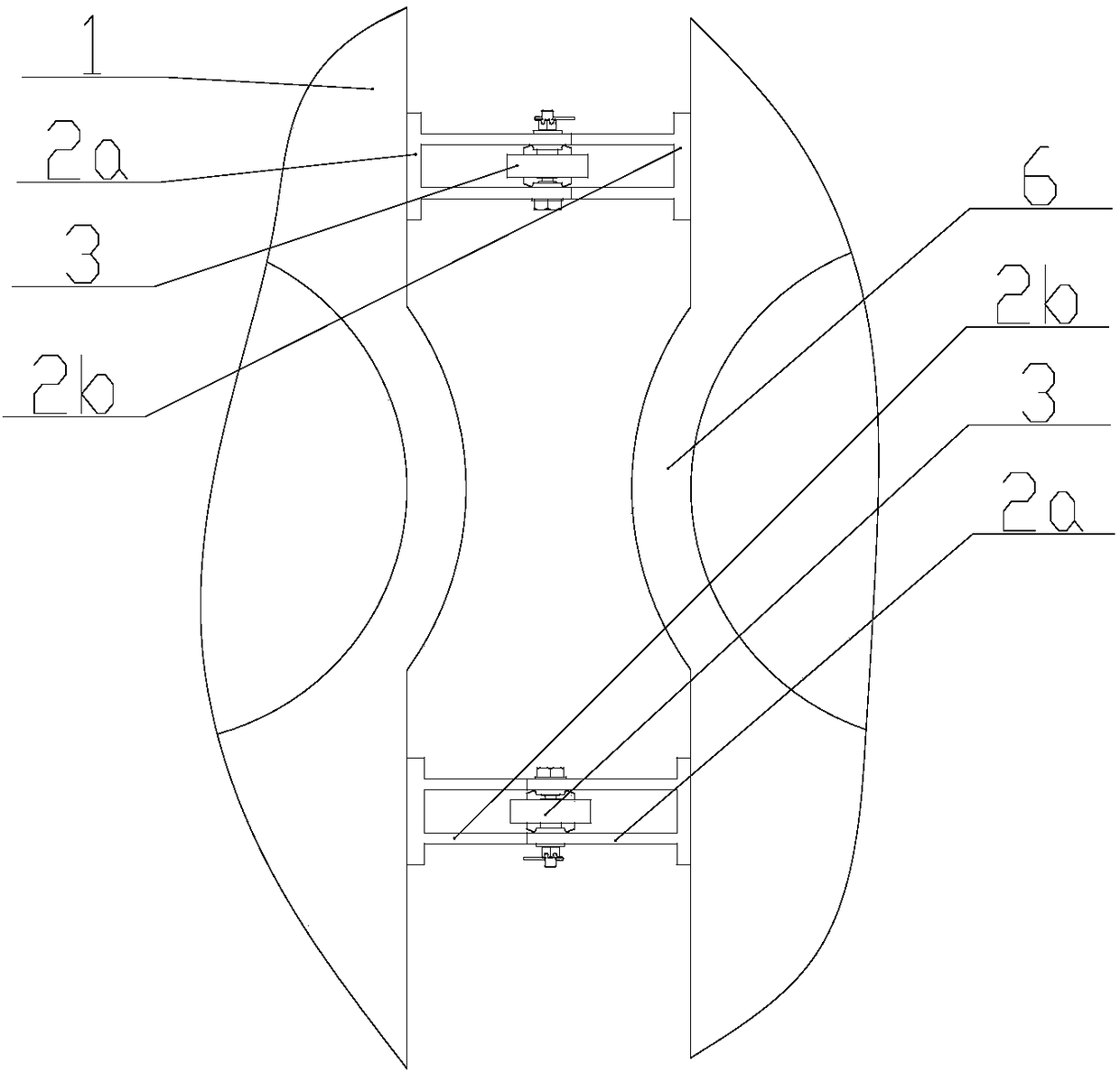
[0031] The core improvement point of the overlapping joint structure for improving redundancy provided by the embodiment of the present invention is that it includes a fixed support and a tie rod structure 3, and its structure can be referred to figure 1 shown;

[0032] The two fixed supports are respectively used to be installed at different heights on the opposite ends of the two adjacent suspension bracket units, such as the left bracket 1 and the right bra...


PUM


Abstract

The invention discloses a lap joint structure used for improving redundancy. A left suspension frame unit and a right suspension frame unit are connected through two lap joint devices. The two lap joint devices are installed in a left and right reversely-arranged mode. When a suspension fault happens to one suspension frame unit, one lap joint device can directly suspend the faulty suspension frame unit, so that the faulty suspension frame unit does not fall to a track, and a line operation fault is avoided. Due to the fact that fixing supports and pull rod structures are connected through knuckle bearings, the longitudinal freedom degree and the transverse freedom degree between the two suspension frame units can be guaranteed, meanwhile, pin shafts are adopted for connection in the pullrod structures, the vertical freedom degree of the two suspension frame units in the uphill and downhill processes can be guaranteed, and the structural uncoupling capacity of a train in the normal linear and bend traveling processes can be guaranteed through the fixing supports and the pull rod structures. The invention further discloses a walking part using the above lap joint structure and themedium-low-speed magnetic levitation train.

Description

technical field [0001] The invention relates to the technical field of magnetic levitation trains, in particular to a lapping device for improving the redundancy of medium and low-speed magnetic levitation trains. Background technique [0002] The running part of the medium and low-speed maglev train is composed of multiple suspension frames. The suspension frame unit is composed of two independent suspension modules, left and right, and an anti-roll decoupling mechanism. The left suspension module and the right suspension module have the same structure and are symmetrically arranged on the left and right tracks. , two independent suspension modules are connected through the anti-roll decoupling mechanism. The suspension frame is an important part of the medium and low-speed maglev train. Each suspension frame is connected to the car body through the air spring on its support arm. [0003] The magnetic levitation train relies on the attractive force generated between the lev...

Claims


Application Information

Patent Timeline
Patent Type & Authority Applications(China)
IPC IPC(8): B60L13/04B61B13/08B61F1/00
CPCB60L13/04B61B13/08B61F1/00
Inventor 向湘林龙志强梁潇周晓明党宁
Owner 湖南轨道技术应用研究中心有限公司
Why Eureka
Try Eureka