Paper binding device

A technology of paper and body, applied in the field of binding machines, can solve problems such as inconvenience of use and environmental restrictions, and achieve the effect of being easy to use

Inactive Publication Date: 2018-09-07
HENAN YUQIAN TECH TRANSFER CENT CO LTD
View PDF1 Cites 0 Cited by
  • Summary
  • Abstract
  • Description
  • Claims
  • Application Information

AI Technical Summary

Problems solved by technology

[0004] In view of the deficiencies in the prior art, the purpose of the present invention is to provide a paper binding device to solve the problem of finding a power source when the prior art needs to be used, and because of the length of the power cord, the use is easily restricted by the environment, resulting in the use of Inconvenient question

Method used


Image

  • Paper binding device
  • Paper binding device

Examples


Embodiment Construction

[0017] In order to make the technical means, creative features, goals and effects achieved by the present invention easy to understand, the present invention will be further described below in conjunction with specific embodiments.

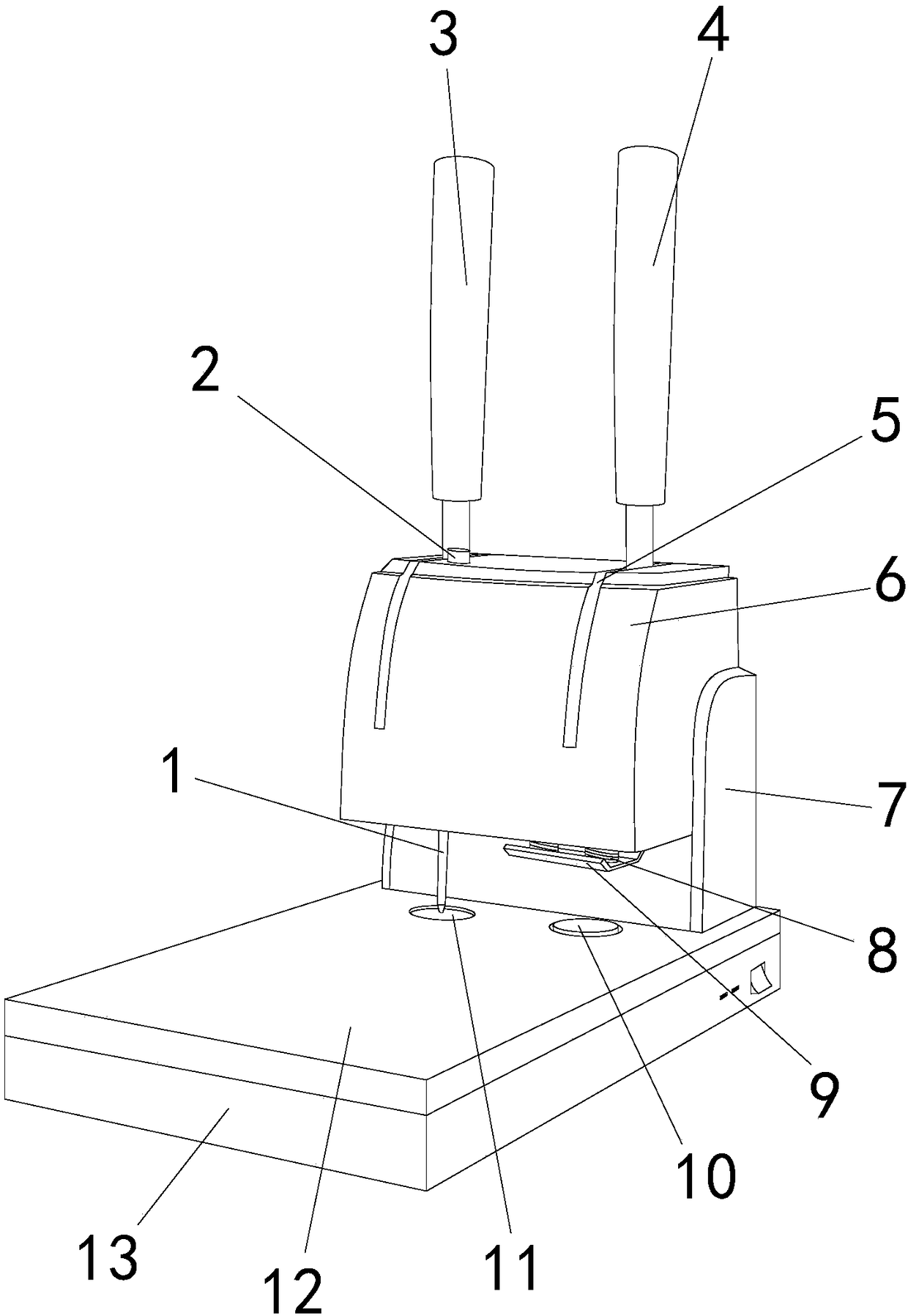
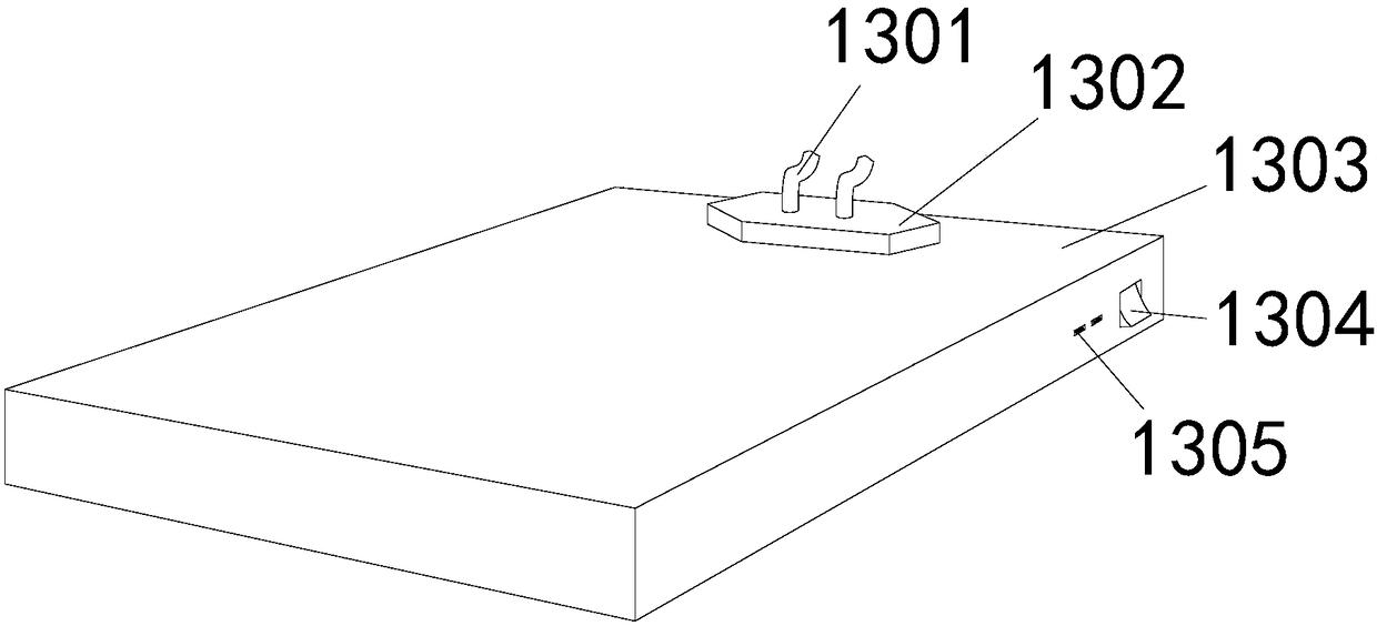
[0018] see figure 1 , figure 2 , the present invention provides a paper binding device: its structure includes a positioning pin 1, a needle head 2, a hot-melt handle 3, a punching handle 4, a handle movable groove 5, a control body 6, a protective plate 7, a punching rod 8, and a limit plate 9 , punching pad 10, hot melt tank 11, workbench 12, battery 13, the control body 6 is an inverted L shape, the horizontal plate is located on the front side, and two arc-shaped handle movable grooves 5 are provided from the front side to the top, so The hot-melt handle 3 is electrically connected with the control body 6 through the handle movable groove 5 on the left side, the punching handle 4 is electrically connected with the control body 6 through the ...


PUM


Abstract

The invention discloses a paper binding device. The paper binding device structurally comprises a positioning needle, a needle head, a hot melt handle, a punching handle, handle moving grooves, a control machine body, a protective plate, punching rods, a limiting plate, a punching pad, a hot melt tank, a working table and a storage battery; the control machine body is in an inverted L shape, and ahorizontal plate is located on the front side; the two arc-shaped handle moving grooves are formed from the front side to the top end, the hot melt handle is electrically connected to the control machine body through the handle moving groove on the left side, and the punching handle is electrically connected to the control machine body through the handle moving groove on the right side; the two punching rods are arranged parallel to each other in the left and right direction, and are connected with the control machine body in a threaded mode; and the limiting plate is installed at the right bottom of the horizontal plate of the control machine body, and is positioned under the punching rods. The paper binding device has the beneficial effects that the storage battery with a current transformer is arranged at the bottom of the working table, so that the device stores electricity when the device is in use and the device is used without the limit of the power source position, the electric connection protection can be carried out, and the use is easy.

Description

technical field [0001] The invention is a paper binding device, which belongs to the field of binding machines. Background technique [0002] Binding machine is a binding equipment that mechanically fixes paper, plastic, leather, etc. with staples or hot melt adhesives, nylon tubes and other materials. Factories, enterprises and institutions financial office, file management and other places. [0003] The prior art discloses a small manual binding machine with an application number of 201520471947.0, which includes a thimble, a workbench, a mobile drill rod, an operating handle, a control box and a driving device, and the thimble is arranged in an annular groove inside the base , the workbench is located above the base and is connected to the annular groove correspondingly. The mobile drill rod is installed in the transmission gearbox and connected to the gear shaft. The operating handle is installed on the frame through the handle fixing seat. Inside, the operating handle...

Claims


Application Information

Patent Timeline
Patent Type & Authority Applications(China)
IPC IPC(8): B42B5/02H02J7/00
CPCB42B5/02H02J7/0068
Inventor 付瑞玲丁普葛小娜
Owner HENAN YUQIAN TECH TRANSFER CENT CO LTD
Why Eureka
Try Eureka