
Clamping flexible manipulator

A manipulator and flexible technology, applied in the field of manipulators, can solve the problems of high difficulty in installation and maintenance, low reliability, waste of time for installation and disassembly, etc., to improve the adsorption and grabbing ability and efficiency, simple control method, and improve clamping force effect

Active Publication Date: 2018-09-07
哈尔滨海特峻煊科技有限公司
View PDF9 Cites 6 Cited by
  • Summary
  • Abstract
  • Description
  • Claims
  • Application Information

AI Technical Summary

Problems solved by technology

[0002] In the field of industrial automation, pneumatic flexible manipulators are often used to achieve grasping actions, but the structure of the current flexible manipulator is relatively complicated, the processing and production costs are high, and the connection and structure of the air intake and ventilation pipelines in the flexible pneumatic manipulator are relatively complicated. The difficulty of installation and maintenance is high, the reliability is low, and the structure for controlling the grabbing direction is relatively complicated, and it is time-consuming to install and disassemble. Flexible manipulators with high manufacturing costs

Method used


Image

  • Clamping flexible manipulator
  • Clamping flexible manipulator
  • Clamping flexible manipulator

Examples


Embodiment Construction

[0035] In order to make the purpose, technical solutions and advantages of the embodiments of the present invention clearer, the technical solutions of the embodiments of the present invention will be clearly and completely described below with reference to the accompanying drawings of the embodiments of the present invention. Obviously, the described embodiments are some, but not all, embodiments of the present invention. Based on the described embodiments of the present invention, all other embodiments obtained by those of ordinary skill in the art fall within the protection scope of the present invention.

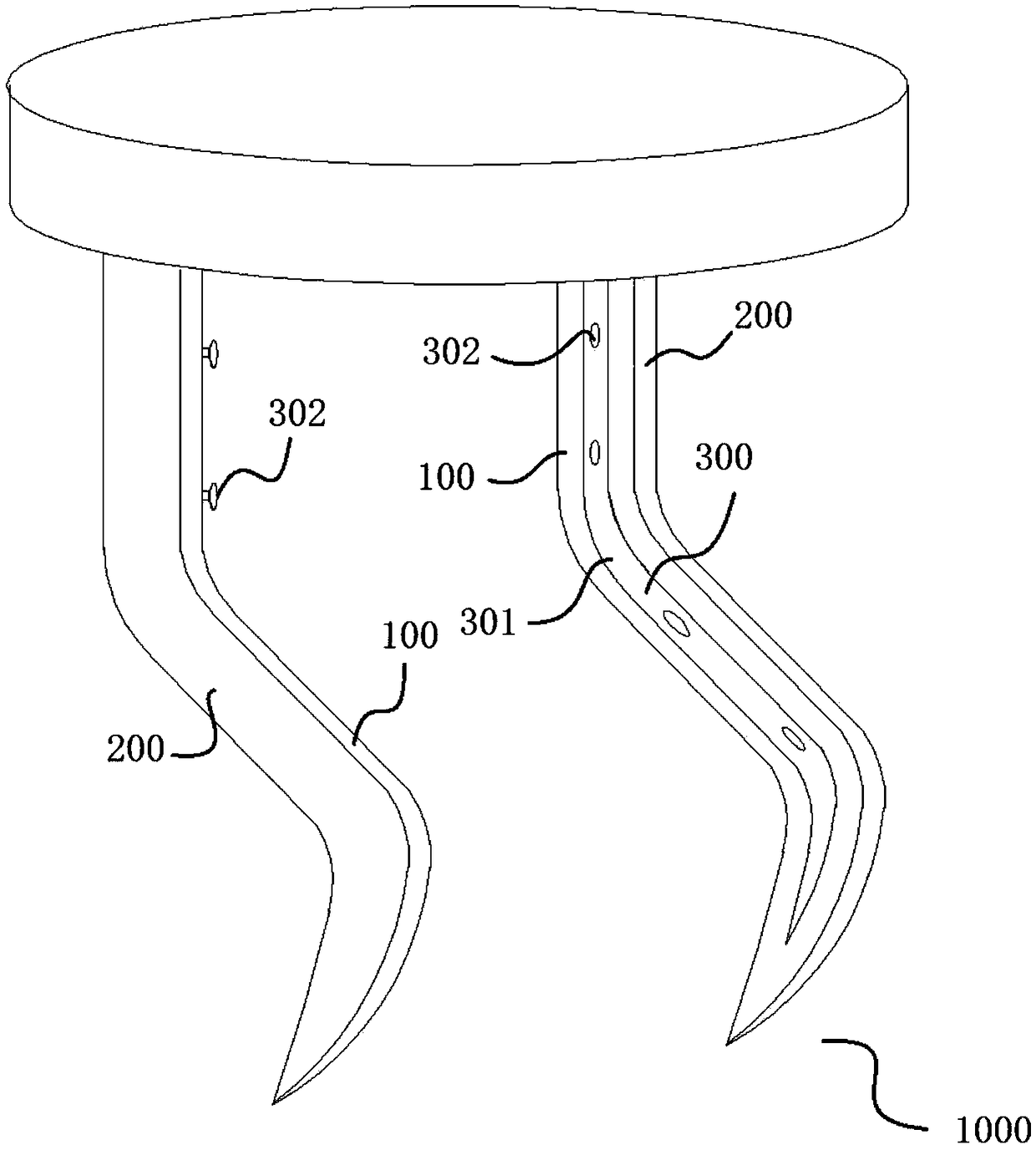
[0036] The flexible gripping manipulator 1000 according to the embodiment of the present invention will be described in detail below with reference to the accompanying drawings.

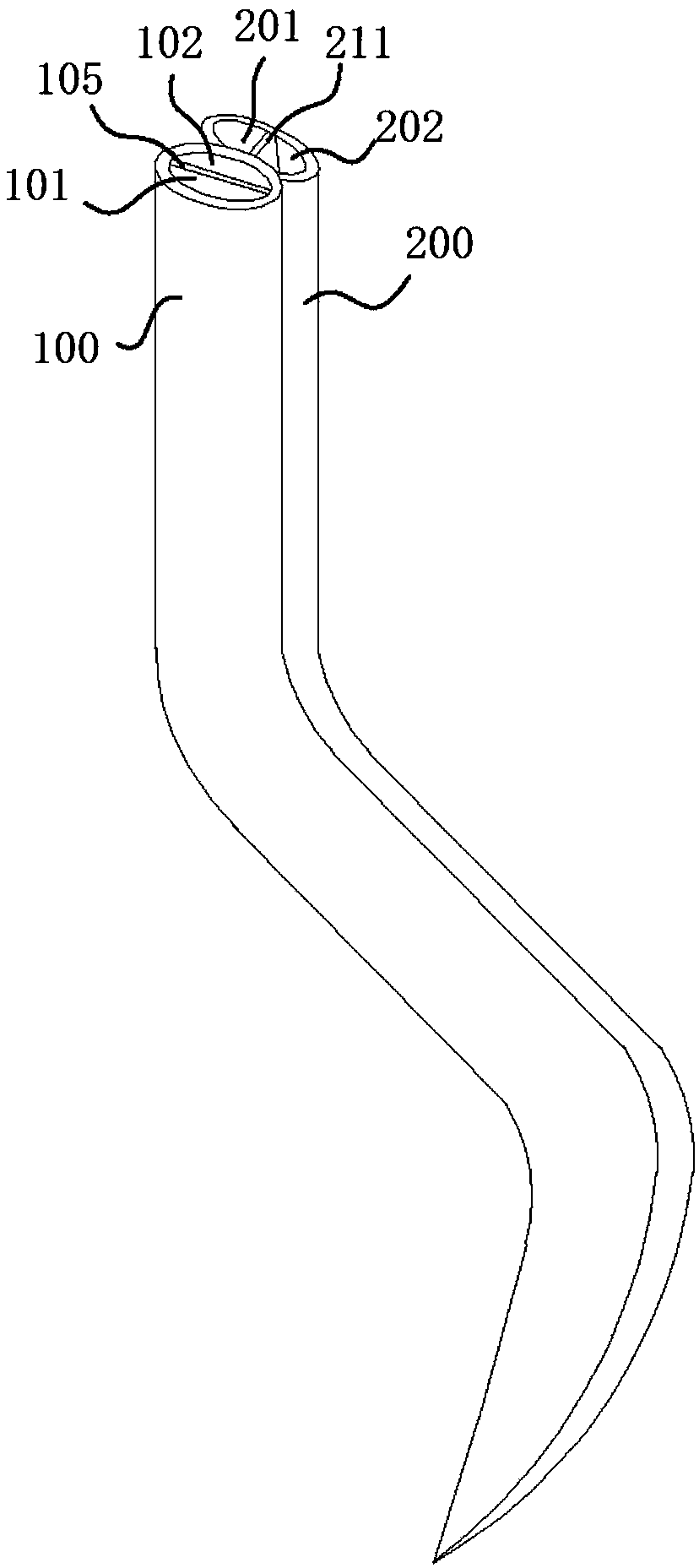
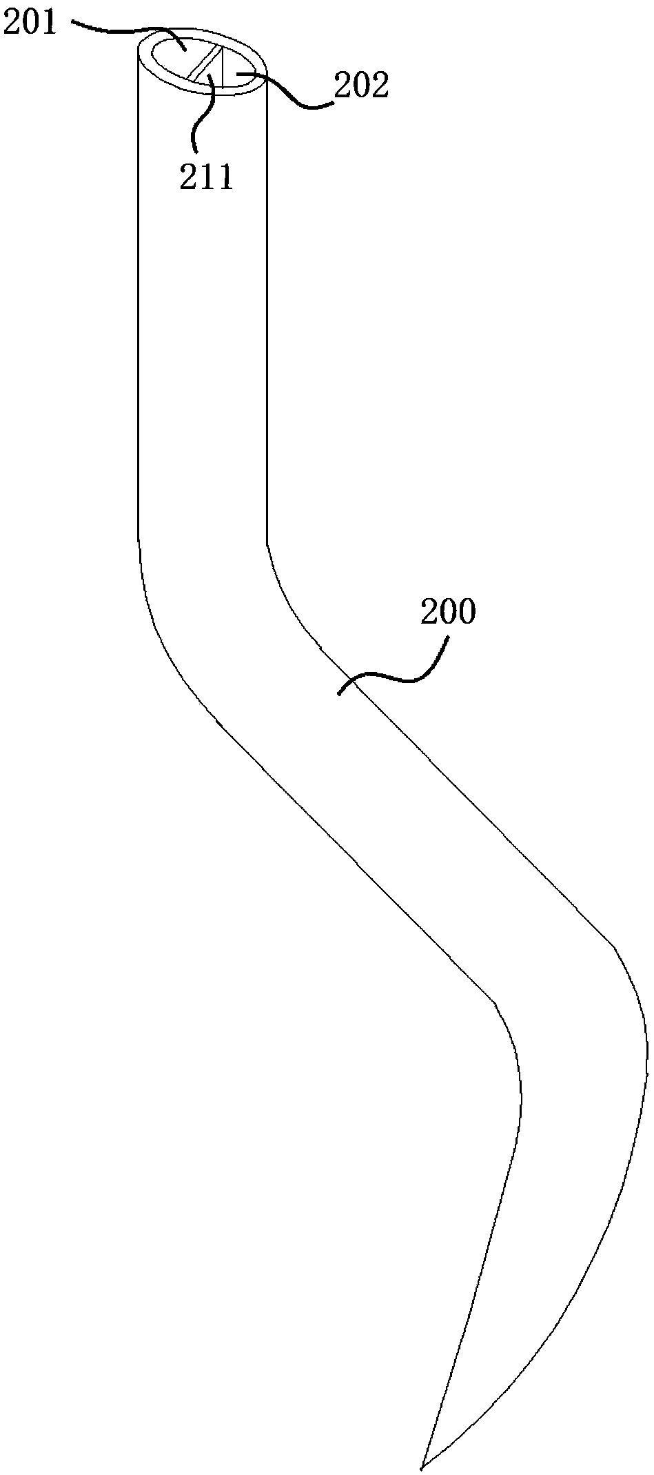
[0037] like Figure 1 to Figure 8 As shown, the clamping flexible manipulator 1000 according to the embodiment of the present invention, used for clamping cylindrical parts, includes at least ...


PUM


Abstract

The invention provides a clamping flexible manipulator. The clamping flexible manipulator comprises first pipe bodies and second pipe bodies, wherein the first pipe bodies are attached to the outer surfaces of cylindrical parts, and the second pipe bodies correspond to the first pipe bodies one by one. First accommodation cavities and second accommodation cavities are formed in the first pipe bodies, wherein the first fluids are arranged in the first accommodation cavities, the first accommodation cavities are close to the cylindrical parts, the second accommodation cavities are arranged opposite to the first accommodation cavities, the second accommodation cavities and the first accommodation cavities are distributed at intervals, second fluids are arranged in the second accommodation cavities, and the first pipe bodies bend towards the sides with the small expansion degree. Third accommodation cavities and forth accommodation cavities are formed in the second pipe bodies, wherein thethird fluids are arranged in the third accommodation cavities, the forth accommodation cavities are arranged opposite to the third accommodation cavities, the third accommodation cavities and forth accommodation cavities are distributed at intervals, forth fluids are arranged in the forth accommodation cavities, and the second pipe bodies bend towards the sides with the small expansion degree. According to the clamping flexible manipulator, the first pipe bodies are combined with the second pipe bodies, a clamping structure is achieved, cylindrical articles can be effectively grasped, and theclamping flexible manipulator has the advantages of simple structures, convenient operation and convenient machining and production.

Description

technical field [0001] The invention relates to the technical field of manipulators, in particular to a clamping flexible manipulator. Background technique [0002] In the field of industrial automation, pneumatic flexible manipulators are often used to realize the grasping action. However, the structure of the current flexible manipulators is relatively complex, the processing and production costs are high, and the connection and structure of the air intake and ventilation pipelines in the flexible pneumatic manipulator are relatively complex. Installation and maintenance are difficult, low reliability, and the structure to control the grasping direction is more complicated, and installation and disassembly are time-consuming. Flexible manipulators that are expensive to manufacture. SUMMARY OF THE INVENTION [0003] In view of this, the present invention provides a clamping flexible manipulator. [0004] In order to solve the above-mentioned technical problems, the pres...

Claims


Application Information

Patent Timeline
IPC IPC(8): B25J15/12B25J15/00B25J15/06
CPCB25J15/00B25J15/06B25J15/0616B25J15/0625B25J15/12
Inventor 李华
Owner 哈尔滨海特峻煊科技有限公司
Learn More