
Direct current brushless motor simulation device and control method thereof

A brushless DC motor and simulation equipment technology, which is applied in simulators, general control systems, motor generator testing, etc., can solve the problems of non-existence of energy interaction, failure to verify the durability and reliability of drive hardware, and achieve guaranteed simulation The effect of precision

Inactive Publication Date: 2018-09-04
SHANGHAI UNIV
View PDF4 Cites 5 Cited by
  • Summary
  • Abstract
  • Description
  • Claims
  • Application Information

AI Technical Summary

Problems solved by technology

This method can freely change the motor parameters and working condition parameters, but obviously there is no real energy interaction in this method, it can only test the software algorithm, and cannot verify the durability and reliability of the drive hardware

Method used


Image

  • Direct current brushless motor simulation device and control method thereof
  • Direct current brushless motor simulation device and control method thereof
  • Direct current brushless motor simulation device and control method thereof

Examples


Embodiment 1

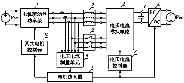
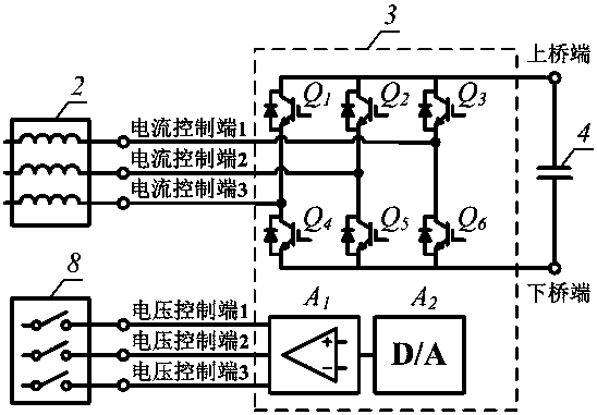
[0053] figure 1 Shown is the system architecture of the brushless DC motor simulation device of the present invention, including a motor driver power stage (1), a load simulation inductor (2), a voltage and current simulation circuit (3), a bus capacitor (4), a DC-DC module ( 5), a voltage and current controller (6), a motor emulator (7), a circuit opening and closing device (8), a voltage and current measurement unit (9) and a real motor controller (10), characterized in that:

[0054] In terms of circuit topology, the output end of the motor driver power stage (1) is connected to one end of the load simulation inductor (2), and the other end of the load simulation inductor (2) is connected to the current control circuit of the voltage and current simulation circuit (3). The output end of the motor driver power stage (1) is connected to one end of the circuit switching device (8), and the other end of the circuit switching device (8) is connected to the voltage of the voltage...

Embodiment 2

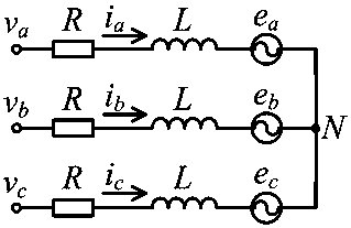
[0062] See figure 1 , Figure 5 and Figure 6 , the control method of the DC brushless motor simulation equipment includes 1), the function of the motor emulator (7) is to solve the DC brushless motor model of known motor parameters in real time, solve the motor state quantity and pass it to the voltage and current control The controller (6) is used to control the voltage and current, and at the same time, the state quantity of the motor is transmitted to the real motor controller (10) for the closed-loop control of the real motor, and to solve the voltage command of the DC-DC module (5); 2), the The voltage and current controller (6) receives the motor state quantity solved by the motor emulator (7) as the command value of the motor simulation, and controls the voltage and current simulation circuit (3) to output the desired voltage and current through the voltage and current tracking algorithm.

[0063] The motor emulator (7) includes a motor simulation algorithm, the moto...


PUM


Abstract

The invention discloses a direct current brushless motor simulation device and a control method thereof. The device comprises a motor driver power stage, a load analog inductor, a voltage and currentanalog circuit, a bus capacitor, a DC-DC module, a voltage and current controller, a motor simulator, a circuit opening and closing device, a voltage and current measuring unit and a real motor controller. The device provided by the invention has the characteristics and advantages that 1) a motor dynamic equation is quickly solved through an estimation-correction numerical integration method, which ensures the real-time performance and satisfies the accuracy of motor simulation; 2) a motor model and corresponding starting or loading parameters thereof are freely configured, and direct currentbrushless motors of various different parameters can be simulated without changing circuit components; and 3) the device is compatible with the control methods of sensored and sensorless direct current brushless motors, and provides corresponding physical quantity feedback.

Description

technical field [0001] The invention relates to a power load simulation device and a control method thereof, in particular to a DC brushless motor simulation device and a control method thereof whose operating parameters can be changed arbitrarily and are compatible with both sensor and sensorless driving methods. Background technique [0002] As one of the most common actuators, motors are widely used in the field of automation. Among them, brushless DC motors are widely used in home appliances and automobile industries because of their large torque-to-volume ratio, no commutation sparks, and high reliability. The motor driver is the core device that drives the motor to run, and usually consists of a drive axle and a drive axle controller. The hardware performance of the driver and the quality of the control algorithm directly affect the working effect of the motor, especially in the automotive industry. The performance of the motor drive unit directly affects the performan...

Claims


Application Information

Patent Timeline
IPC IPC(8): G05B17/02G01R31/00G01R31/34
CPCG01R31/00G01R31/34G05B17/02
Inventor 刘畅何永义
Owner SHANGHAI UNIV
Learn More