
Cloud deck

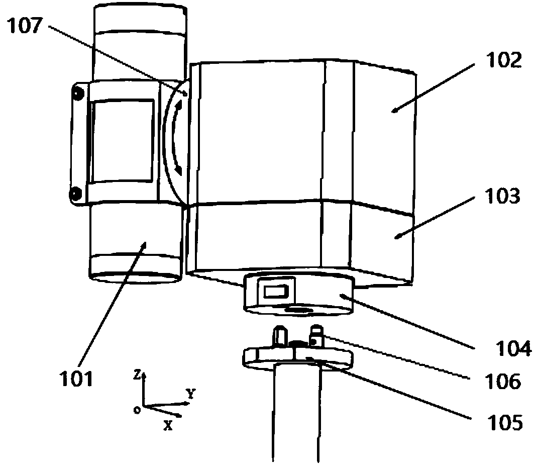
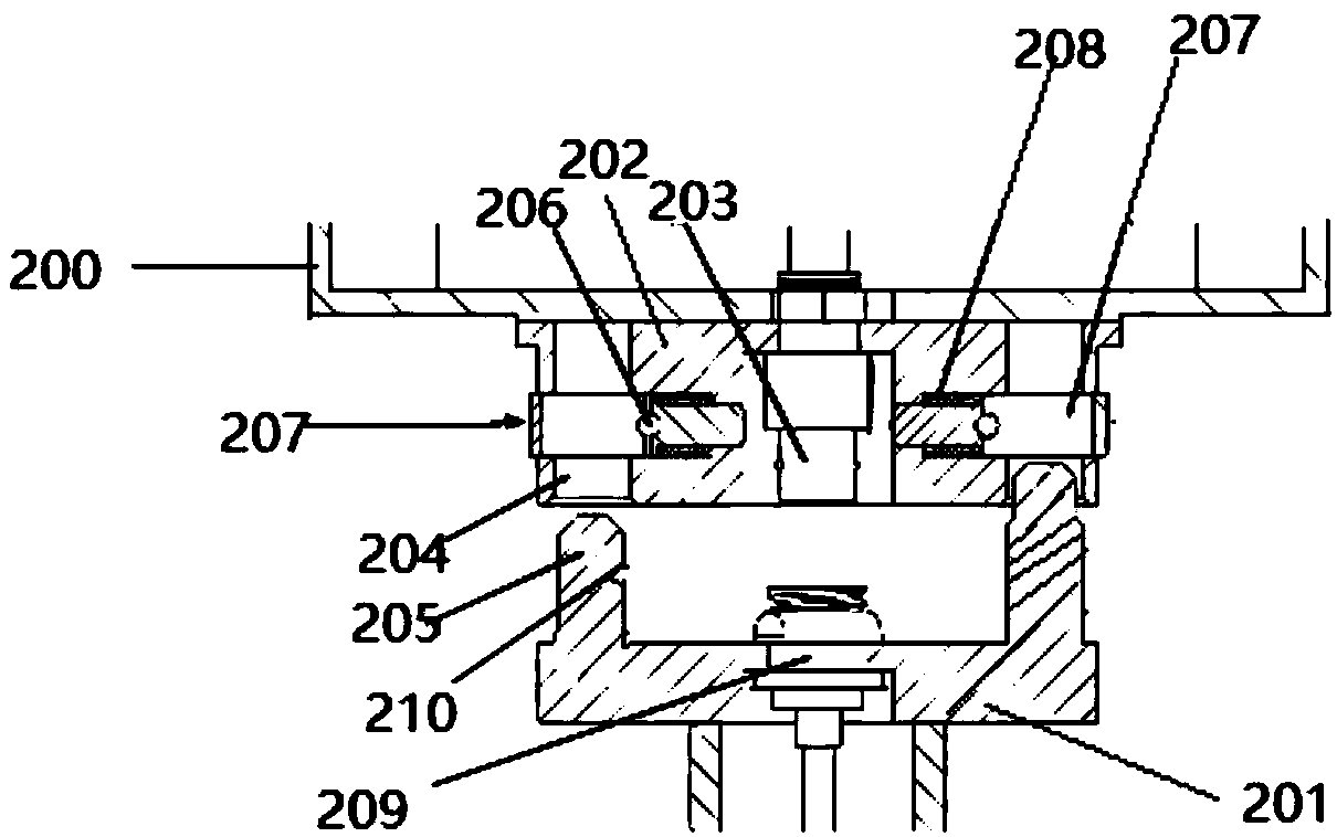
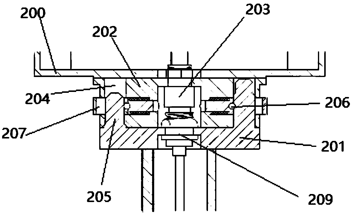
A technology of pan/tilt and annular boss, applied in machine/stand, camera, coupling device, etc., can solve the problems of large installation space, large size of industrial pan/tilt, twisting and winding, etc.

Pending Publication Date: 2018-09-04
BEIJING XUANYU INTELLIGENT TECH CO LTD
View PDF6 Cites 3 Cited by
  • Summary
  • Abstract
  • Description
  • Claims
  • Application Information

AI Technical Summary

Problems solved by technology

However, the pan / tilt is generally screwed and fixed on the support, and there are a large number of complicated cables arranged in the pan / tilt system. It is impossible to quickly disassemble and reinstall in an ordinary industrial environment, not to mention that it needs to be installed by a heavy manipulator. nuclear radiation environment
On the other hand, in order to prevent the twisting and winding of the internal cables, the existing pan / tilts are usually designed so that the angle range of reciprocating swing in the horizontal direction is within ±180° at most, and the angle range of pitching action in the vertical direction is within ±100°. The photoelectric switch is used to limit the position. Therefore, the commonly used industrial pan / tilt is not only large in size, complex in structure, and large in installation space, but also unable to perform two-degree-of-freedom continuous rotation, which severely limits the shooting angle and range.

Method used


Image

  • Cloud deck
  • Cloud deck
  • Cloud deck

Examples


Embodiment Construction

[0028] The following description and drawings illustrate specific embodiments of the invention sufficiently to enable those skilled in the art to practice them. The examples merely represent possible variations. Individual components and functions are optional unless explicitly required, and the order of operations may vary. Portions and features of some embodiments may be included in or substituted for those of other embodiments. The scope of embodiments of the present invention includes the full scope of the claims, and all available equivalents of the claims. Various embodiments herein are described in a progressive manner, each embodiment focuses on the differences from other embodiments, and the same and similar parts of the various embodiments may be referred to each other. As for the structures, products, etc. disclosed in the embodiments, since they correspond to the parts disclosed in the embodiments, the description is relatively simple, and for relevant parts, ple...


PUM


Abstract

The invention discloses a cloud deck which comprises a camera shooting device, a box, a locking mechanism and a support. The camera shooting device is fixedly connected to one side face of the box through a flange, the box comprises an upper box body and a lower box body, and the upper box body is rotationally and fixedly connected to the lower box body; the locking mechanism is fixed to the bottom face of the lower box body, the support is provided with a locking connecting piece matched with the locking mechanism, the locking mechanism is an annular boss protruding out of the bottom of the lower box body, a cable plug is arranged in the center of the annular boss, a plurality of positioning pin holes are further formed in the bottom face of the annular boss, a sliding groove hole is formed in the side wall of each positioning pin hole, a sliding lock cylinder is arranged in each sliding groove hole, a long groove hole is formed in the middle portion of each lock cylinder, a protruding block is arranged on the side wall of each long groove hole, positioning pins on the support penetrate the long groove holes of the lock cylinders, the protruding blocks on the side walls of the long groove holes are buckled into grooves of the positioning pins, and the cloud deck is locked to the support. The cloud deck can be quickly detached and installed, and the cloud deck can be maintainedand repaired conveniently.

Description

technical field [0001] The invention relates to the technical field of imaging devices, in particular to a high-precision servo platform that can be quickly assembled and disassembled. Background technique [0002] The pan / tilt used in the general industrial environment usually uses a motor to drive the worm gear to form a transmission system. The positioning accuracy of the pan / tilt is generally between 0.1° and 5° (it is called a high-precision pan / tilt when the positioning accuracy is not greater than 0.5°), and the photoelectric encoder is used. Realize closed-loop control. The photoelectric devices installed in existing industrial pan / tilts have an extremely short normal working life in a nuclear radiation environment, and their safety and reliability cannot be guaranteed when used in a nuclear radiation environment, such as a hot cell. Therefore, even on the basis of ordinary industrial pan / tilt, the shielding and sealing of the pan / tilt shell to the radiation environ...

Claims


Application Information

Patent Timeline
Patent Type & Authority Applications(China)
IPC IPC(8): F16M11/12F16M11/18G03B17/56H01R13/627
CPCH01R13/627G03B17/561F16M11/121F16M11/18
Inventor 李硕张韬懿范立明张道理
Owner BEIJING XUANYU INTELLIGENT TECH CO LTD
Learn More