Intelligent load relieving device

An intelligent and mitigation technology, applied in the load mitigation system and structural engineering fields, can solve the problems of large seasonal temperature difference, small mitigation range, and low line fault troubleshooting efficiency, and achieve energy saving, large mitigation range, and easy maintenance.

Pending Publication Date: 2018-09-04
HENAN UNIVERSITY
View PDF0 Cites 1 Cited by
  • Summary
  • Abstract
  • Description
  • Claims
  • Application Information

AI Technical Summary

Problems solved by technology

[0003] The purpose of the present invention is to propose an intelligent load easing device to solve the problems of the catenary load buffering device in the above-mentioned prior art, such as small easing range, large influence of seasonal temperature difference, and low line fault troubleshooting efficiency. The technical solution is: an intelligent load mitigation device, including a support frame composed of left main frame side plates, right main frame side plates and intermediate connectors, and roller mechanisms, Air cylinder, air pump and storage battery, the piston rod of the air cylinder is arranged towards the direction of the roller mechanism, the roller mechanism includes a rotating shaft, and a driving pulley, a first buffer pulley and a second buffer pulley are fixed on the rotating shaft, the first The buffer pulley and the second buffer pulley are distributed on both sides of the driving pulley, and the two ends of the rotating shaft are respectively connected to the corresponding left main frame side plate or right main frame side plate; Both the buffer pulley and the second buffer pulley are wound with a buffer cable, the free end of the active cable is used to be fixed on the engineering structure, the free end of the buffer cable is fixed on the piston rod, and the rear end of the support frame There are lugs for fixing on immovable objects outside the engineering structure; the air pump provides the air pressure power source for the air cylinder, and the battery provides power for the work of the air cylinder and the air pump

Method used


Image

  • Intelligent load relieving device
  • Intelligent load relieving device

Examples


Embodiment Construction

[0016] The present invention will be further described below in conjunction with the accompanying drawings.

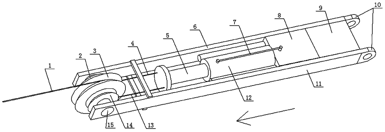
[0017] Such as figure 1 As shown, an intelligent load mitigation device includes a support frame composed of the left main frame side plate 11, the right main frame side plate 6 and intermediate connectors, and in the support frame from the front end to the rear end, that is, along the direction of the arrow A Roller mechanism, air cylinder 12, air pump 8 and accumulator 9 are installed successively, and the piston rod 5 of described air cylinder 12 is arranged toward the direction of roller mechanism, and described roller mechanism comprises rotating shaft 15, and driving pulley 3, The first buffer pulley 2 and the second buffer pulley 14, the first buffer pulley 2 and the second buffer pulley 14 are distributed on both sides of the drive pulley 3, and the two ends of the rotating shaft 15 are respectively connected to the corresponding left main frame side plate 11 o...


PUM


Abstract

The invention discloses an intelligent load relieving device, and belongs to the technical field of load relieving systems in the field of structural engineering. The intelligent load relieving devicecomprises a supporting frame composed of a left main frame side plate, a right main frame side plate and a middle connecting piece, the supporting frame is internally and sequentially provided with arolling wheel mechanism, a pneumatic cylinder, a pneumatic pump and a storage battery from the front end to the rear end, and a piston rod of the pneumatic cylinder is arranged towards the rolling wheel mechanism; the rolling wheel mechanism comprises a rotating shaft, a driving pulley, a first buffer pulley and a second buffer pulley are fixed on the rotating shaft, the first buffer pulley and the second buffer pulley are distributed on the two sides of the driving pulley correspondingly, and the two ends of the rotating shaft are rotationally connected with the corresponding left main frameside plate or the corresponding right main frame side plate separately; and a driving pulling cable is wound around the driving pulley, and buffer pulling cables are wound around the first buffer pulley and the second buffer pulley. According to the intelligent load relieving device, whether the faults of the device such as cable breaking occurs or not can be judged according to the pulling forceof the pulling cables and the displacement change of the pulling cables, and the cable breaking position is obtained, so that maintenance is convenient.

Description

technical field [0001] The invention belongs to the technical field of load mitigation systems in the field of structural engineering, and in particular relates to an intelligent load mitigation device. Background technique [0002] The design idea of ​​the load mitigation system is to add a movable device to the engineering structure. When the load changes, the movable device can automatically undergo adaptive movement, thereby adjusting the structural shape and converting the internal energy of the structure into external energy. , to adapt to the change of load and achieve the purpose of self-protection. In recent years, with the rapid development of my country's rail transit, load mitigation devices have been widely used in electrical engineering catenary. At present, the existing load relaxation devices are mainly divided into four categories, which are pulleys, springs, rod-springs, wheel-springs, etc. There are many shortcomings in the actual application process, suc...

Claims


Application Information

Patent Timeline
Patent Type & Authority Applications(China)
IPC IPC(8): F15B15/20
CPCF15B15/20
Inventor 杜文风杜志豪朱黎明王龙轩贺鹏斐赵艳男
Owner HENAN UNIVERSITY
Why Eureka
Try Eureka