Adjustable concrete laser milling machine

A technology for concrete and milling machines, applied in the field of milling machines, can solve problems such as inability to mix and mix concrete, inefficient cooling means of milling rotors, influence of machine operations, etc. Effect

Inactive Publication Date: 2018-09-04
JIANGSU KERUIXIN MACHINERY
View PDF0 Cites 2 Cited by
  • Summary
  • Abstract
  • Description
  • Claims
  • Application Information

AI Technical Summary

Problems solved by technology

[0002] Road milling machine is one of the main types of asphalt pavement maintenance construction machinery and one of the main equipment for asphalt concrete pavement maintenance construction. It can be used to remove defects such as road bumps, oil waves, reticulation, and ruts; the existing laser milling machines have certain disadvantages when they are used. First, the existing milling machines cannot be deployed while they are working. The concrete is mixed for use. Secondly, the current cooling method for the milling rotor is not so efficient. Finally, the motor will vibrate up and down when it is working. The vibration will affect the operation of the machine and bring a certain impact to the user. To this end, we propose an adjustable concrete laser milling machine

Method used


Image

  • Adjustable concrete laser milling machine
  • Adjustable concrete laser milling machine
  • Adjustable concrete laser milling machine

Examples


Embodiment Construction

[0017] In order to make the technical means, creative features, goals and effects achieved by the present invention easy to understand, the present invention will be further described below in conjunction with specific embodiments.

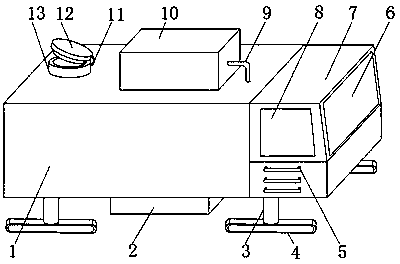
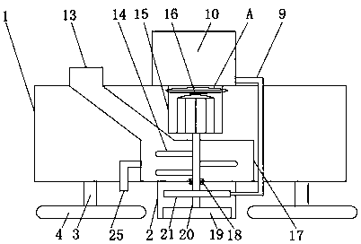
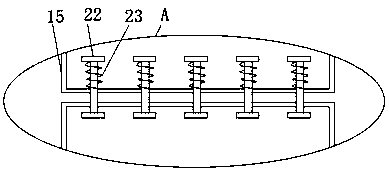
[0018] Such as Figure 1-4 As shown, an adjustable concrete laser milling machine includes a vehicle body 1 and a headstock 7, one side of the outer surface of the body 1 is fixedly connected to the outer surface of the headstock 7, and a window 6 is fixedly installed on the other side of the outer surface of the headstock 7. , and the outer surface of the front end of the headstock 7 is movably installed with a door 8, the handle 5 is welded below the door 8, the outer surface of the lower end of the vehicle body 1 is fixedly installed with a connecting pillar 3, and the outer surface of the lower end of the connecting pillar 3 is movably installed with a track wheel 4 , the outer surface of the upper end of the vehicle body 1 is provided with a ...


PUM


Abstract

The invention discloses an adjustable concrete laser milling machine. The adjustable concrete laser milling machine comprises a vehicle body and a vehicle head, wherein a vehicle window is fixedly mounted on the outer surface of the other side of the vehicle head; a vehicle door is movably mounted on the outer surface of the front end of the vehicle head; a handle is welded below the vehicle door;a connecting support is fixedly mounted on the outer surface of the lower end of the vehicle body; a crawler wheel is movably mounted on the outer surface of the lower end of the connecting support;a feeding opening is formed in the outer surface of the upper end of the vehicle body; a connecting belt is fixedly connected with the outer surface of one side of the feeding opening; a feeding opening plug plate is fixedly connected with one end, far away from the feeding opening, of the outer surface of one end of the connecting belt. The adjustable concrete laser milling machine disclosed by the invention is provided with a motor mounting frame, a water spraying mechanism and a stirring mechanism, so that concrete can be stirred when milling work is carried out on a road surface; in a working process, the cooling efficiency of a milling rotor is higher and the vibration generated in a working process of the motor can be reduced, so that a better application prospect is brought.

Description

technical field [0001] The invention relates to the field of milling machines, in particular to an adjustable concrete laser milling machine. Background technique [0002] Road milling machine is one of the main types of asphalt pavement maintenance construction machinery and one of the main equipment for asphalt concrete pavement maintenance construction. It can be used to remove defects such as road bumps, oil waves, reticulation, and ruts; the existing laser milling machines have certain disadvantages when they are used. First, the existing milling machines cannot be deployed while they are working. The concrete is mixed for use. Secondly, the current cooling method for the milling rotor is not so efficient. Finally, the motor will vibrate up and down when it is working. The vibration will affect the operation of the machine and bring a certain impact to the user. To this end, we propose an adjustable concrete laser milling machine. Contents of the invention [0003] ...

Claims


Application Information

Patent Timeline
Patent Type & Authority Applications(China)
IPC IPC(8): E01C23/088B28C5/08B28C5/16
CPCE01C23/0885B28C5/0806B28C5/16
Inventor 蔡敦军
Owner JIANGSU KERUIXIN MACHINERY
Why Eureka
Try Eureka