Robot conveying hanging bracket

A technology of robots and hangers, which is applied in the field of robots, can solve problems such as unsafety, robot shaking up and down, and inability to maintain stability, and achieve the effects of reducing potential accidents, reducing resonance phenomena, and avoiding shaking

Active Publication Date: 2018-09-04
WUHU YIZE SMALL & MEDIUM ENTERPRISE PUBLIC SERVICE CO LTD
View PDF7 Cites 3 Cited by
  • Summary
  • Abstract
  • Description
  • Claims
  • Application Information

AI Technical Summary

Problems solved by technology

[0003] According to the announcement number 106985164A, an intelligent robot transportation board is proposed. According to the instructions, "the ends of the first splint and the second splint away from the first connecting rod and the second connecting rod are fixedly connected with rubber pads, and the first splint and the second The outer surface of the splint is curved to improve the temperature of the overall clamping intelligent robot. During the movement of the base, it can effectively prevent the robot from moving and improve the overall rationality. There are certain defects in it, because the rubber pad belongs to The parts that are easy to wear will break and perforate under the impact force for a long time, so that it cannot guarantee that the base can effectively prevent the robot from moving during the movement process.
[0004] The current robot transportation equipment is not equipped with a corresponding buffer and shock-absorbing mechanism, which causes the robot to shake up and down due to vibration during the handling process, and cannot maintain stability in the air, so there are potential safety accidents

Method used


Image

  • Robot conveying hanging bracket
  • Robot conveying hanging bracket
  • Robot conveying hanging bracket

Examples


Embodiment Construction

[0021] The following will clearly and completely describe the technical solutions in the embodiments of the present invention with reference to the accompanying drawings in the embodiments of the present invention. Obviously, the described embodiments are only some, not all, embodiments of the present invention. Based on the embodiments of the present invention, all other embodiments obtained by persons of ordinary skill in the art without making creative efforts belong to the protection scope of the present invention.

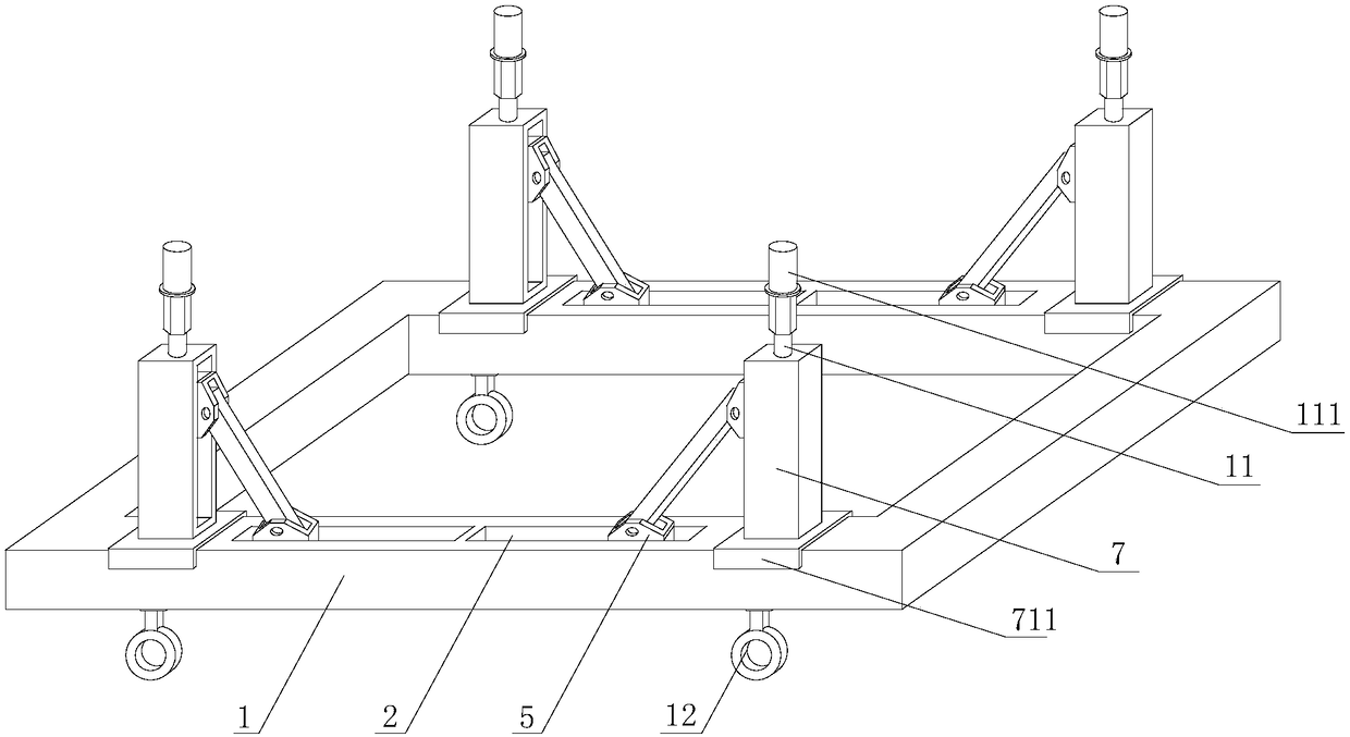
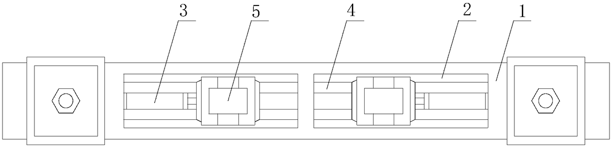
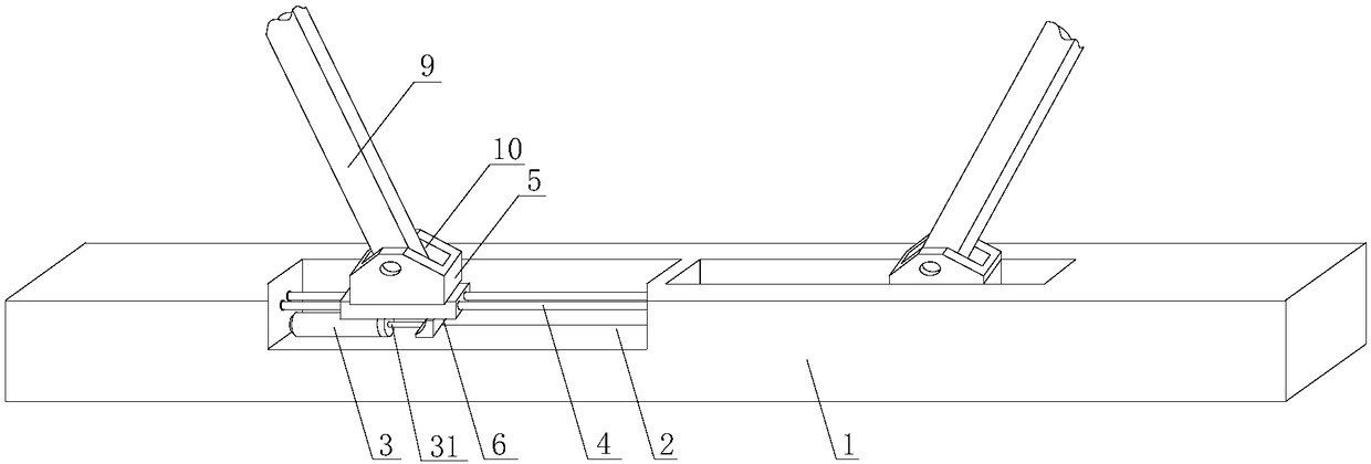
[0022] see Figure 1-4 , a robot transport hanger, comprising a square steel frame 1 and a steel rope sling 11, a groove 2 is provided on the plate surface of the square steel frame 1, a damper 3 is installed at the bottom of the groove 2, and the middle part of the groove 2 A screw mandrel 4 is installed, and a first connector 5 is slidably installed on the screw mandrel 4, and the connecting end of the first connector 5 extends out of the groove 2; a connect...


PUM


Abstract

The invention discloses a robot conveying hanging bracket. The robot conveying hanging bracket comprises a square steel frame and a steel rope hanging cable. Grooves are formed in the plate surface ofthe square steel frame. A damper is mounted at the bottom of each groove. A screw rod is mounted in the middle of each groove. A first connecting piece is mounted on each screw rod in a sliding manner. The connecting end of each first connecting piece extends out of the corresponding groove. A connecting head is mounted on a piston rod at one end of each damper. The upper end of each connecting head is fixedly connected with the bottom of the corresponding first connecting piece. A vibration reduction mechanism is further arranged on the plate surface of the square steel frame. According to the robot conveying hanging bracket, force borne by the steel rope hanging cable is counteracted through deformation of vibration reduction springs, and thus the resonance phenomenon of the steel ropehanging cable is reduced; power for pushing second connecting pieces to move is consumed through the dampers, so that the vibration damping purpose is achieved, and thus stability of the hanging bracket is further improved; and the hanging bracket is in the steady state, and robot hoisting stability is guaranteed.

Description

technical field [0001] The invention relates to the technical field of robots, in particular to a robot transport hanger. Background technique [0002] Robot is the most prominent representative product of artificial intelligence. It is a machine device that performs work automatically. It can assist or replace human work according to the set procedures, such as production, construction, or work in dangerous environments. With the development of modern technology, in order to improve the stability of the robot, it is usually a base method added at the bottom of the robot to increase the stability of the overall placement. [0003] According to an intelligent robot transportation board proposed by the announcement number 106985164A, according to the instructions, "the ends of the first splint and the second splint away from the first connecting rod and the second connecting rod are fixedly connected with rubber pads, and the first splint and the second The outer surface of t...

Claims


Application Information

Patent Timeline
Patent Type & Authority Applications(China)
IPC IPC(8): B66C1/16F16F15/04B66C13/06
CPCB66C1/16B66C13/06F16F15/04
Inventor 赵文娟赵文波
Owner WUHU YIZE SMALL & MEDIUM ENTERPRISE PUBLIC SERVICE CO LTD
Why Eureka
Try Eureka