
Patsnap Eureka
For R&D, Patsnap Eureka makes reading and utilizing patents & technical documents easy.
Patsnap Eureka AIR
Designed for self-driven R&D workflows. Generate viable solutions, solve complex R&D challenges, empower your innovation with AI.

Patsnap Eureka Materials
Designed for material experts only. Revolutionize your material R&D, from search, analyze, to developing new materials.

TechResearch
Generate reliable direction feasibility study reports for your R&D in just a few steps.

TechSeek
Discover and master advanced knowledge NOW. Basics, ideas, possibilities, all at once.

TechMind
As an expert in R&D Theories, TechMind can generates customized viable solutions instantly.

TechRisk
Analyze your overall solution with one click, know your potential R&D risks in advance.

TechMonitor
Get weekly tech updates, stay abreast of the latest tech innovations and key insights.
Nut demounting machine
A nut machine and nut technology, applied in ceramic molding machines, unloading devices, metal processing, etc., can solve the problems of increased labor costs, reduced work efficiency, inconvenient use, etc., and achieves strong practicability, low cost, and high precision Effect
- Summary
- Abstract
- Description
- Claims
- Application Information
AI Technical Summary
Problems solved by technology
Method used
Image

Examples
Embodiment 1
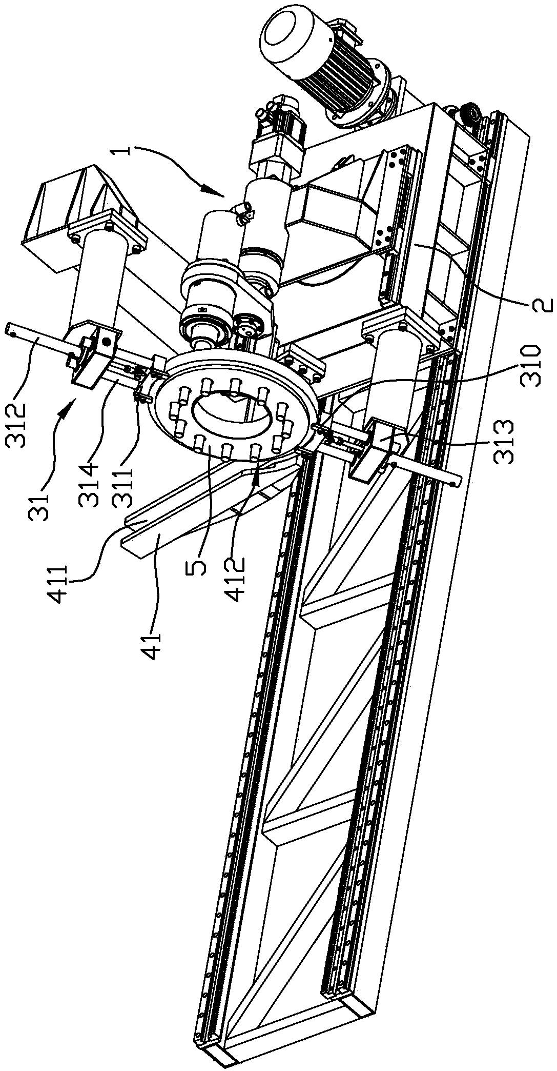
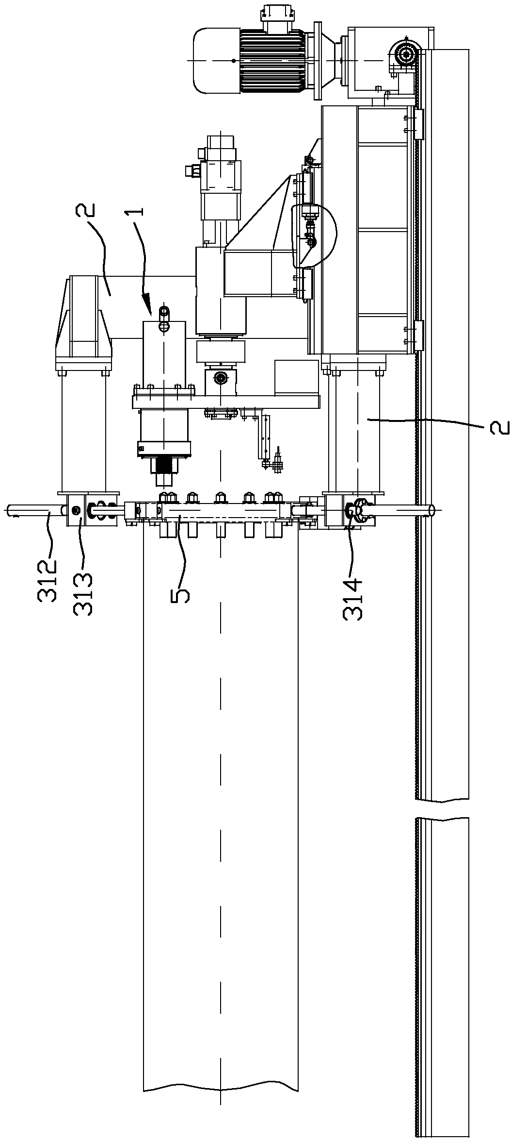
[0030] Such as Figures 1 to 6 As shown, it is the first embodiment of the present invention, the nut removal machine of this embodiment includes an organic platform 2, a fixing structure for clamping the end plate 5 of the pipe mold and being arranged on the machine platform 2 and facing the end The nut on the plate 5 is disassembled and the nut assembly 1, the conveying device that can remove the end plate 5, wherein,
[0031] The fixed structure is arranged on the machine platform 2, and the fixed structure is a clamping mechanism 31 which is arranged oppositely and clamps the end plate 5 of the pipe mold. The clamping mechanism 31 includes a clamping part 311 adapted to the outer peripheral edge of the end plate 5 and a first driving mechanism 312 that drives the clamping part 311 to move. The first driving mechanism 312 is an oil cylinder, an air cylinder or other driving mechanisms , in this embodiment, the first driving mechanism 312 is an air cylinder. In order to al...
Embodiment 2
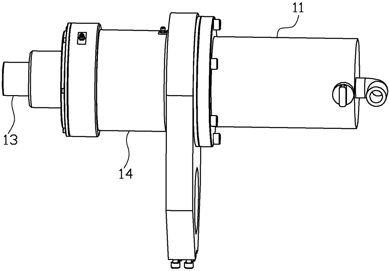
[0042] Such as Figure 7 to Figure 11 As shown, it is the second embodiment of the present invention. The difference between this embodiment and the above-mentioned embodiment one is: a. The circumferential limit structure between the demoulding shaft 12 and the output shaft 111 of the motor 11 is different: the motor 11 The output shaft 111 of the output shaft 111 is inserted in the socket 122 of the demoulding shaft 12, and the outer peripheral wall of the output shaft 111 and the inner peripheral wall of the socket 122 are correspondingly provided with a keyway 110, and the two keyways 110 are connected by a key (such as a flat key) so that the output shaft 111 and the demoulding shaft 12 are circumferentially limited.
[0043] b. The axial limit structure between the demoulding shaft 12 and the output shaft 111 of the motor 11 is different: a step portion 123 is formed on the inner wall of the demoulding shaft 12, and a stop piece 124 is provided on the front end of the st...
PUM
 Abstract
Description
Claims
Application Information
 - R&D Engineer
- R&D Manager
- IP Professional
- Industry Leading Data Capabilities
- Powerful AI technology
- Patent DNA Extraction
Browse by: Latest US Patents, China's latest patents, Technical Efficacy Thesaurus, Application Domain, Technology Topic, Popular Technical Reports.
© 2024 PatSnap. All rights reserved.Legal|Privacy policy|Modern Slavery Act Transparency Statement|Sitemap|About US| Contact US: help@patsnap.com