Nut demounting machine

A nut machine and nut technology, applied in ceramic molding machines, unloading devices, metal processing, etc., can solve the problems of low production efficiency, time-consuming and laborious, etc., and achieve the effects of high production efficiency, simple process and strong practicability

Pending Publication Date: 2018-09-04
周兆弟
View PDF16 Cites 1 Cited by
  • Summary
  • Abstract
  • Description
  • Claims
  • Application Information

AI Technical Summary

Problems solved by technology

[0004] After the nuts on the fixed end plate of the pipe mold of the above-mentioned nut removal machine are removed, the fixed end plate and bolts need to be recovered and cleaned for next use. In the prior art, after the nuts are removed, the bolts are directly scattered to the ground, or hung On the bolt hole of the fixed end plate, it needs to be removed manually to realize the separation of the end plate and the bolt, and then the two are manually transported to the next process for cleaning or recycling. After nuts, it is necessary to manually separate the end plate and bolts and transfer them to the next process, which is time-consuming and laborious, resulting in low production efficiency

Method used


Image

  • Nut demounting machine
  • Nut demounting machine
  • Nut demounting machine

Examples


Embodiment 1

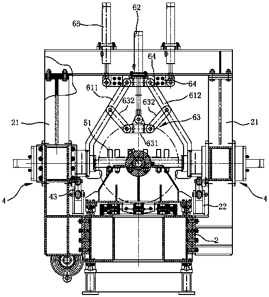
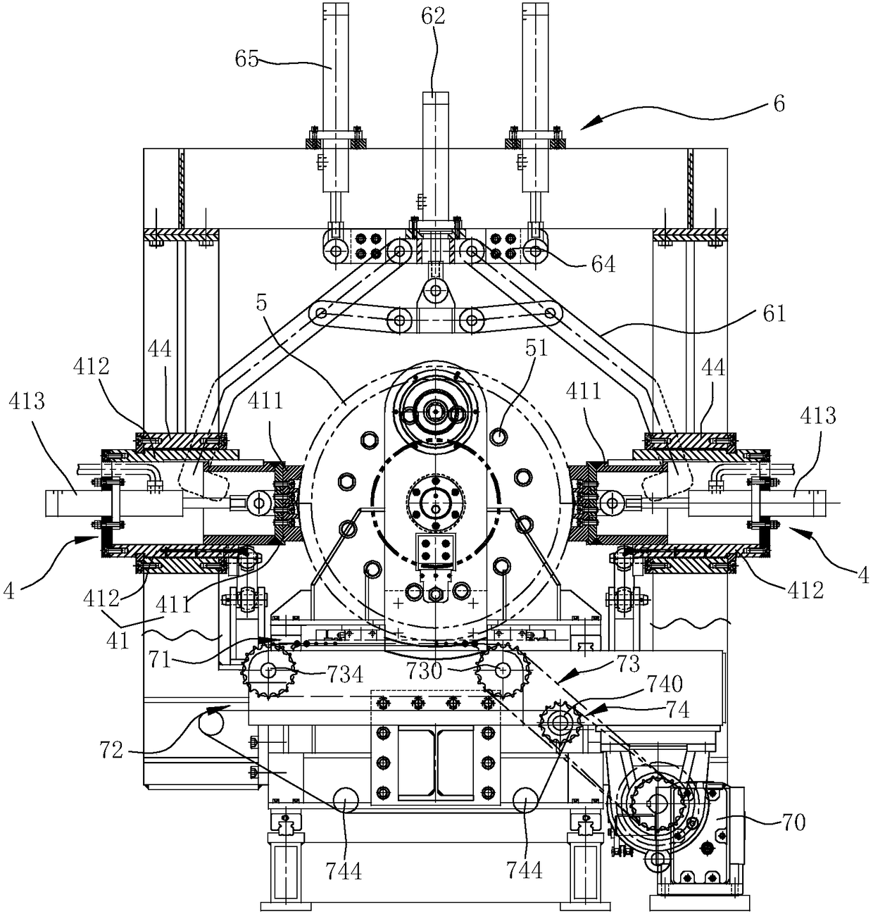
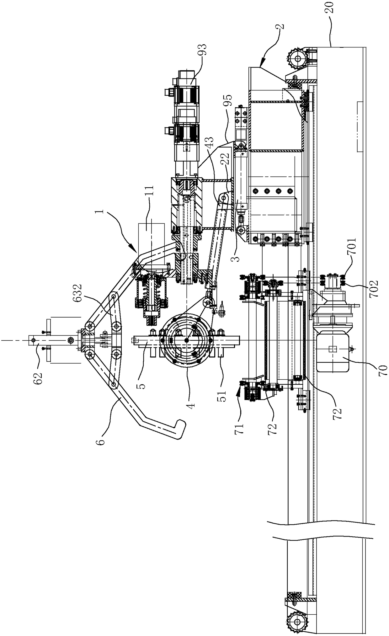
[0047] like Figure 1 to Figure 15 Shown is the first embodiment of the present invention. The nut removal machine of this embodiment includes an organic platform 2, a nut removal assembly 1 that is arranged on the machine platform 2 and disassembles the nuts on the end plate 5, a first drive mechanism 3, a turning mechanism 4 and a conveying mechanism, and a clamping mechanism. Take the clamping mechanism 6 of the end plate 5, wherein,

[0048] In this embodiment, the nut removal assembly 1 is arranged on the first support 95 of the machine table 2, and the first support 95 is provided with a ninth driving mechanism 951 for driving the nut removal assembly 1 to approach or move away from the end plate 5, and the nut removal The assembly 1 moves under the drive of the ninth driving mechanism 951 to facilitate the disassembly of the nuts on the end plate; specifically, when the nuts on the end plate are removed, the ninth driving mechanism drives the nut removal assembly 1 clo...

Embodiment 2

[0077] like Figure 16 to Figure 22 As shown, it is the second embodiment of the present invention. The difference between this embodiment and the above-mentioned embodiment one is: a. The first conveying mechanism 71 is fixedly connected with the second conveying mechanism 72, and the power output end of the seventh driving mechanism 70 A first sprocket 701 is connected, and the first sprocket 701 is in transmission connection with the first transmission mechanism 73 and is used to drive the first conveying mechanism 71 and the second conveying mechanism 72 to move synchronously.

[0078] b. The circumferential limit structure between the demoulding shaft 12 and the output shaft 111 of the air motor 11 is different: the output shaft 111 of the motor 11 is inserted into the socket 122 of the demoulding shaft 12, and the outer peripheral wall of the output shaft 111 and The inner peripheral walls of the insertion holes 122 are respectively provided with key grooves 110, and the...


PUM


Abstract

The invention relates to a nut demounting machine. The nut demounting machine comprises a machine table, a nut demounting assembly, a first drive mechanism, turnover mechanisms, a first conveying mechanism and a second conveying mechanism. The nut demounting assembly is arranged on the machine table and used for demounting nuts on an end plate. The first drive mechanism is used for driving the nutdemounting assembly to move front and back and providing space for turning over the end plate. The turnover mechanisms can turn over the end plate and separate the end plate from a bolt. The first conveying mechanism is used for conveying the end plate to the next procedure. The second conveying mechanism is used for conveying the bolt to the next procedure. The turnover mechanisms of the nut demounting machine turn over the end plate and automatically separate the end plate from the bolt, and the end plate and the bolt are automatically conveyed to the next procedures of the end plate and the bolt through the conveying mechanisms; the procedures are simple, operation is easy, the bolt does not need to be demounted manually, time and labor are saved, and the production efficiency is improved; and the bolt and the end plate can be cyclically used, meanwhile, the nut demounting assembly can move in the axial direction of the end plate, the space is provided for turning over the end plate, and the situation that components are damaged due to interference during turnover of the nut demounting assembly and the end plate is avoided.

Description

technical field [0001] The invention belongs to the field of prefabricated component production equipment in building technology, and in particular relates to a nut removal machine for pipe mold end plates. Background technique [0002] In the production of pipe piles, one end of the pipe form is provided with a fixed end plate, and the fixed end plate is connected with the main reinforcement of the steel cage in the pipe pile through several nuts. Usually, the nuts are evenly arranged along the circumference of the fixed end plate. During the demoulding process, the nuts on the fixed end plate need to be removed. In the traditional technology, workers hold a jackhammer (pneumatic nut remover) to remove the nuts on the fixed end plate one by one, which is inefficient and time-consuming. [0003] For example, the patent No. ZL201610113470.8 (the publication number is CN105666685A) discloses a "small nut machine for dismantling and fixing the end plate of the pipe mold". The ...

Claims


Application Information

Patent Timeline
Patent Type & Authority Applications(China)
IPC IPC(8): B23P19/06
CPCB23P19/06B28B21/90B28B13/065
Inventor 周兆弟
Owner 周兆弟
Why Eureka
Try Eureka