
Control box device capable of preventing airflow leakage and keeping uniform temperature

A technology of uniform temperature and control box, applied in the direction of laboratory utensils, shells or chambers, heating or cooling equipment, etc. The effect of improving the density, improving the utilization rate and improving the uniformity

Pending Publication Date: 2018-09-04
爱斯佩克试验仪器(广东)有限公司
View PDF0 Cites 0 Cited by
  • Summary
  • Abstract
  • Description
  • Claims
  • Application Information

AI Technical Summary

Problems solved by technology

[0003] In the prior art, the inner wall of the test environment chamber of the high and low temperature test chamber is usually set with a metal plate structure. During the process of alternating high and low temperature cold and heat or the humidity test process, a large amount of mist will be formed in the environmental chamber. When encountering the metal inner wall When it accumulates to a certain extent, the condensed water will fall to the bottom wall of the environmental cavity or the surface of the test product under the action of gravity, affecting the test results of the test product

Method used


Image

  • Control box device capable of preventing airflow leakage and keeping uniform temperature
  • Control box device capable of preventing airflow leakage and keeping uniform temperature
  • Control box device capable of preventing airflow leakage and keeping uniform temperature

Examples


Embodiment Construction

[0039] The present invention will be described in detail below in conjunction with the accompanying drawings and embodiments.

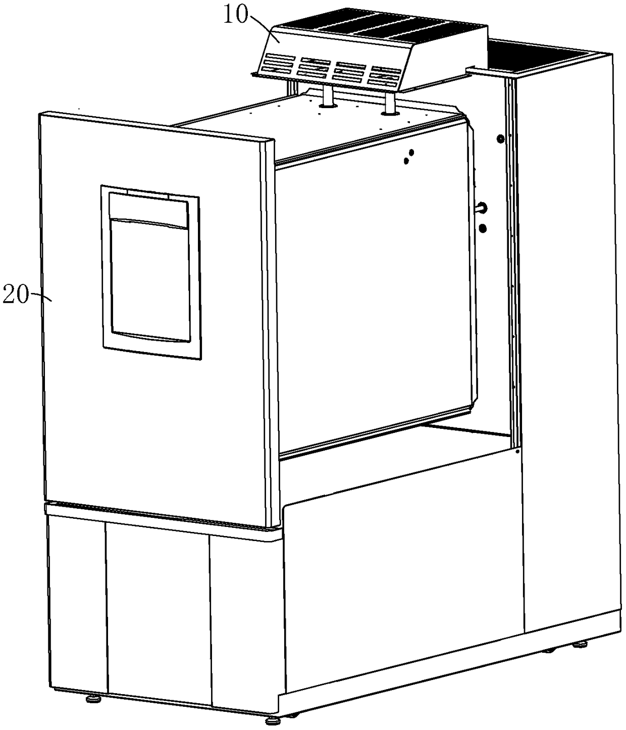
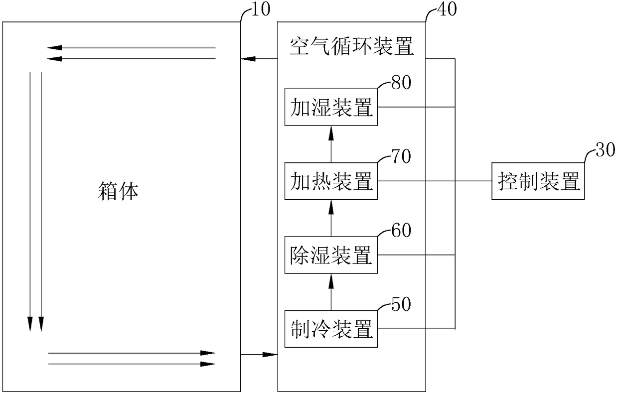
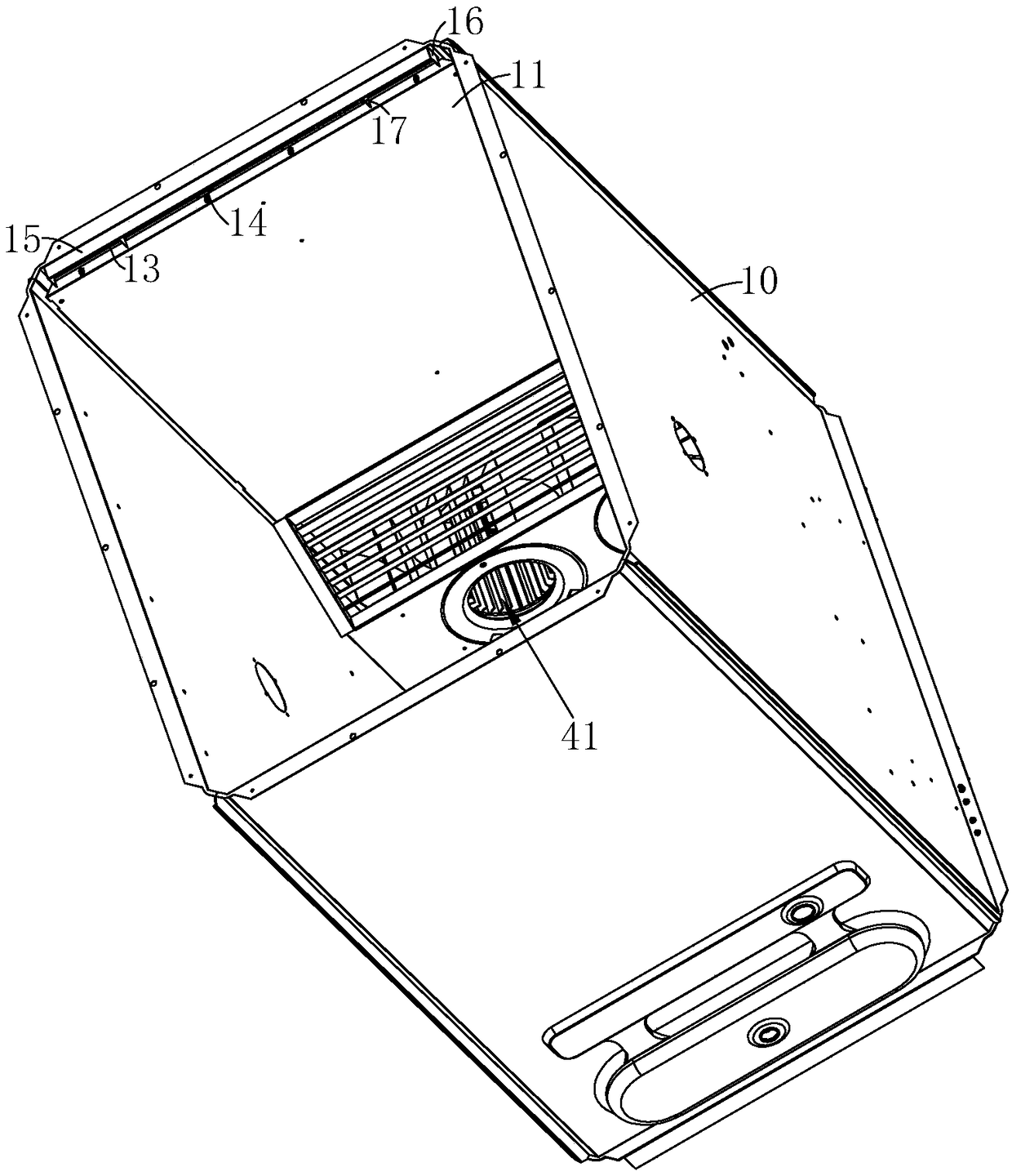
[0040] A device with airflow prevention and uniform temperature control box, see figure 1 and figure 2 , including a box body 10, a box door 20, a control device 30, an air circulation device 40, a refrigeration device 50, a dehumidifying device 60, a heating device 70 and a humidifying device 80, wherein the box door 20 is arranged on the front of the box body 10, and the box body The door 20 is hinged on the box door 20, and the product is placed in the inner cavity of the box body 10. The control device 30 is used to control the operation of the air circulation device 40, the refrigeration device 50, the dehumidification device 60, the heating device 70 and the humidification device 80, and the air circulation The device 40 flows the gas in the box body 10 by sending hot air and moisture into the inner cavity of the box body 10 and extracting the...


PUM

PropertyMeasurementUnit
Thicknessaaaaaaaaaa

Abstract

The invention discloses a control box device capable of preventing airflow leakage and keeping uniform temperature, aiming at the problem that condensed water falls to the surface of a tested rticle under the action of gravity, the control box device is characterized by comprising a box body, a box door and an air feeding device, wherein the box door is rotatably connected onto the front side of the box body, the air feeding device is arranged at the top of the back surface of the box body and used for feeding hot air into an inner cavity of the box body, an air feeding hole of the air feedingdevice faces the box door, the box body is internally fixedly connected with a partitioning plate for separating a product from the top surface of the inner cavity of the box body, the air feeding hole of the air feeding device is provided with the partitioning plate and is used for introducing hot air into the top and bottom of the separating plate, a wind deflector is fixedly connected to the side surface, far away from the air feeding device, of the partitioning plate and is used for blocking hot air flowing through the partitioning plate and introducing the hot air below the partitioningplate, and a plurality of separation plates are fixedly connected to the side surface, far away from the air feeding device, of the partitioning plate and are used to separate an air outlet formed bythe partitioning plate and the top surface of the inner cavity of the box body. The control box device has the advantages of preventing water condensation and airflow leakage and keeping uniform temperature.

Description

technical field [0001] The invention relates to a high and low temperature test box, more specifically, it relates to a box device with airflow prevention and uniform temperature control. Background technique [0002] As a commonly used environmental testing equipment at present, the high and low temperature test chamber mainly provides test environments and tests for electronic components, industrial materials, and finished products in the research and development, production, and inspection of various links such as mutual constant heat and complex high and low temperature Conditions, suitable for quality testing in various industries such as electronic appliances, communications, chemicals, hardware, rubber, furniture, toys, scientific research, etc. [0003] In the prior art, the inner wall of the test environment chamber of the high and low temperature test chamber is usually set with a metal plate structure. During the process of alternating high and low temperature col...

Claims


Application Information

Patent Timeline
IPC IPC(8): B01L1/00B01L7/00
CPCB01L1/00B01L7/00B01L2300/18
Inventor 梶口宜弘
Owner 爱斯佩克试验仪器(广东)有限公司
Learn More