Eureka AIR delivers breakthrough ideas for toughest innovation challenges, trusted by R&D personnel around the world.

Intelligent monitoring fire protection device

A fire-fighting device and intelligent monitoring technology, applied in fire rescue and other fields

Inactive Publication Date: 2018-09-04
泉州市联政信息科技有限公司
View PDF0 Cites 1 Cited by
  • Summary
  • Abstract
  • Description
  • Claims
  • Application Information

AI Technical Summary

Problems solved by technology

[0005] Aiming at the deficiencies of the existing technology, the purpose of the present invention is to provide an intelligent monitoring fire-fighting device to solve the problem that when the existing technology is used, with the rapid development of the economy and society, people have a stronger awareness of fire protection. Fire alarm systems and other fire protection measures have been installed in buildings and public places; the existing gas fire extinguishing alarm system is mainly composed of fire alarm devices and devices with other auxiliary functions. The fire detector triggers the alarm device through the smoke generated in the combustion stage and the temperature rise caused by the fire, so as to detect the occurrence of the fire, and the nozzle performs surrounding eruption to extinguish the fire, and the fire is extinguished uniformly, but the initial fire is divided into strong and weak points, If the fire can be targeted at the main concentrated points of the fire, the effect of fire extinguishing will be better, and the time for extinguishing the fire will be reduced, which can further reduce the problem of losses.

Method used


Image

  • Intelligent monitoring fire protection device
  • Intelligent monitoring fire protection device
  • Intelligent monitoring fire protection device

Examples


Embodiment Construction

[0024] In order to make the technical means, creative features, goals and effects achieved by the present invention easy to understand, the present invention will be further described below in conjunction with specific embodiments.

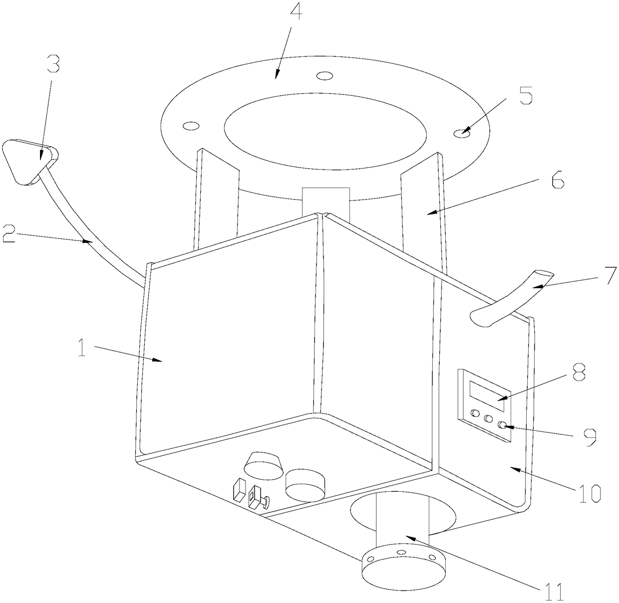
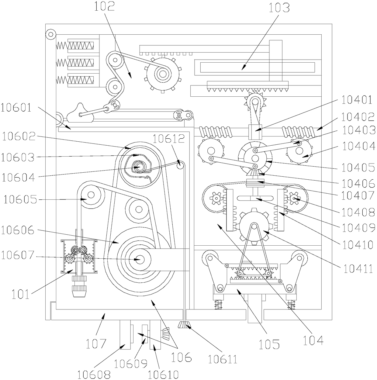
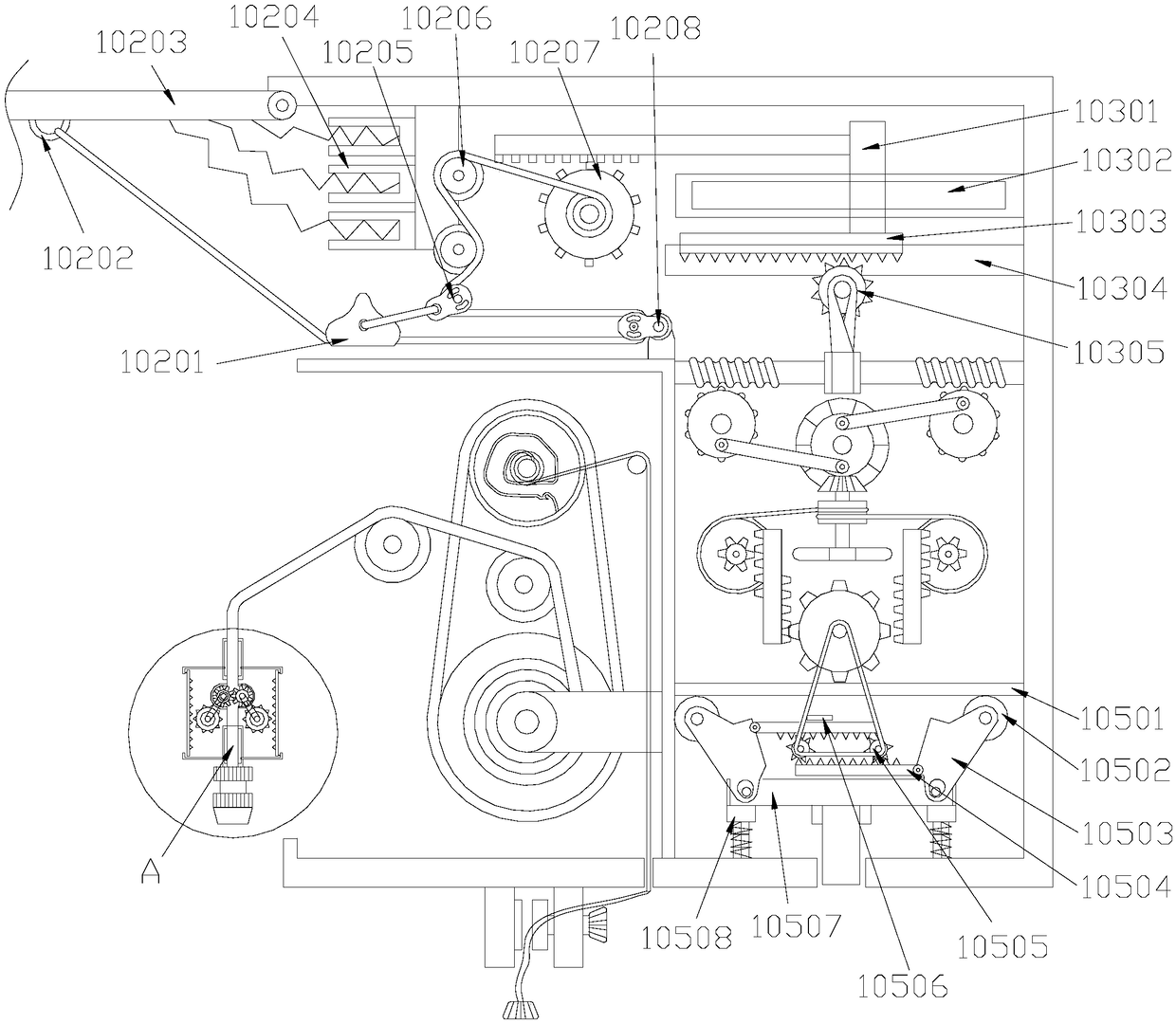
[0025] see Figure 1-Figure 4 , the present invention provides a technical solution for an intelligent monitoring fire-fighting device: its structure includes a fire-fighting device 1, an electric wire 2, a triangular plug 3, a suspension ring 4, a threaded hole 5, a support connecting plate 6, a water inlet pipe 7, a display screen 8, and a control button 9 , smoke temperature control induction box 10, induction nozzle 11, threaded holes 5 are provided on the suspension ring 4, the lower end surface of the suspension ring 4 is welded to the support connecting plate 6 and the two are perpendicular to each other, the support connecting plate 6 The lower end is welded to the upper end of the fire fighting device 1 and the two are perpendicular to ea...


PUM


Abstract

The invention discloses an intelligent monitoring fire protection device. The intelligent monitoring fire protection device structurally comprises a fire protection device, a wire, a triangular plug,a lifting ring, a threaded hole, a supporting connecting plate, a water inlet pipe, a display screen, a control button, a flue gas temperature control sensing box and a sensing spray head; the threaded hole is formed in the lifting ring; the lower end face of the lifting ring and the supporting connecting plate are welded, and the lifting ring and the supporting connecting plate are vertical to each other; the lower end of the supporting connecting plate and the upper end face of the fire protection device are welded, and the supporting connecting plate and the fire protection device are vertical to each other; the back end face of the fire protection device is electrically connected with the triangular plug through the wire; the right end of the fire protection device is connected with the left end of the flue gas temperature control sensing box; a water inlet pipe is arranged on the front end face of the flue gas temperature control sensing box; and the display screen and the controlbutton are arranged on the front end face of the flue gas temperature control sensing box. According to the fire protection device, a side plate is opened by a T-shaped bearing plate and through a spring and a water flow accelerating spray head structure sprays water on fire focus points, so that flame is extinguished easily, the fire extinction time is reduced and loss can be further reduced.

Description

technical field [0001] The invention is an intelligent monitoring fire-fighting device, which belongs to the field of fire-fighting equipment. Background technique [0002] Fire monitoring is the main responsibility of building firefighters. Building firefighters refer to firefighters who are engaged in fire safety management of buildings and structures, fire prevention inspection, and operation and maintenance of building fire protection facilities. [0003] Building firefighters refer to firefighters who are engaged in fire safety management of buildings and structures, fire prevention inspection, and operation and maintenance of building fire protection facilities. Their main occupational functions are: fire inspection; monitoring of fire control room; operation and maintenance of building fire protection facilities ; Fire safety management, according to the scope of occupational activities, work responsibilities and work difficulty of practitioners, they are divided into...

Claims


Application Information

Patent Timeline
IPC IPC(8): A62C31/02A62C31/28
CPCA62C31/02A62C31/28
Inventor 黄建富
Owner 泉州市联政信息科技有限公司
Why Eureka
Eureka Blog
Learn More