
An electroluminescence display panel, its manufacturing method and display device

A technology of electroluminescent display and manufacturing method, which is applied in the direction of circuits, electrical components, static indicators, etc., can solve the problems of difficult process, high difficulty, high cost, etc., and achieve the effect of eliminating the problem of jagged display

Active Publication Date: 2021-02-26
BOE TECH GRP CO LTD +1
View PDF3 Cites 0 Cited by
  • Summary
  • Abstract
  • Description
  • Claims
  • Application Information

AI Technical Summary

Problems solved by technology

However, limited by the FMM process itself, the method of FMM with special-shaped edges is costly and difficult, and the process is not easy to realize

Method used


Image

  • An electroluminescence display panel, its manufacturing method and display device
  • An electroluminescence display panel, its manufacturing method and display device
  • An electroluminescence display panel, its manufacturing method and display device

Examples


Embodiment Construction

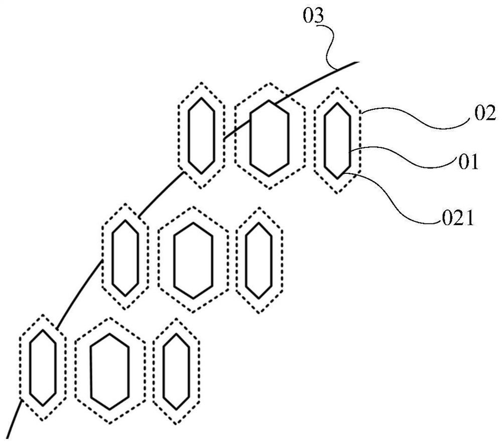
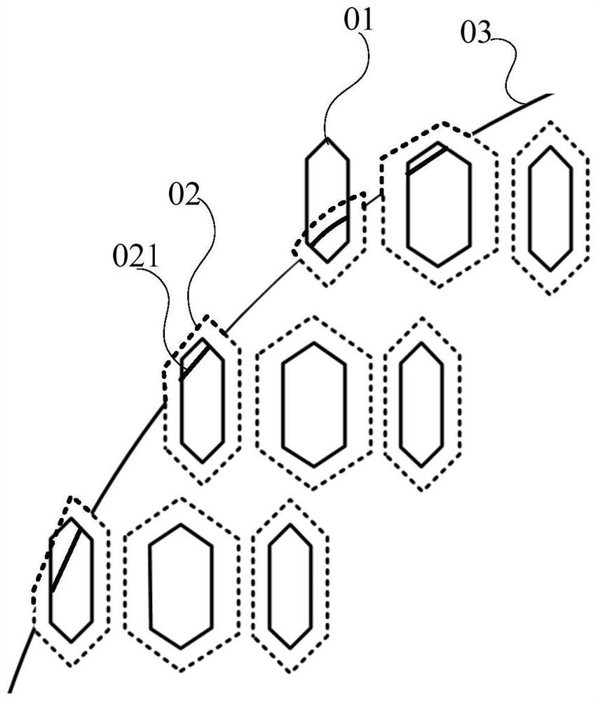
[0044] Specifically, such as figure 1 As shown, in the special-shaped display area, the opening area 01 of the pixel defining layer used to define the light emitting area of ​​the sub-pixel is arranged in steps. figure 1 In the illustration, the shape of each opening area 01 is a hexagon surrounded by a solid line as an example. Correspondingly, the hollow area 021 of the FMM used to make the light-emitting functional layer 02 of the sub-pixel is consistent with the shape and size of the opening area 01 of the pixel definition layer, that is, the two overlap each other. Due to the shadow area (Shadow) in the evaporation process, the pattern of the final light-emitting functional layer 02 is larger than the hollow area 021 of the FMM. figure 1 The hexagon surrounded by dotted lines in the diagram indicates the pattern of the produced light-emitting functional layer 02 . Since the opening area 01 of the pixel definition layer is arranged in steps at the ideal edge 03 of the sp...


PUM


Abstract

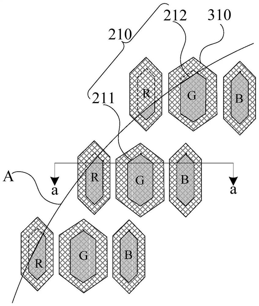
The invention discloses an electroluminescent display panel, its manufacturing method and a display device. Since the opening area of ​​the pixel defining layer defines the shape of the light-emitting area of ​​the sub-pixel, by changing the shape of the opening area at the edge of the abnormally-shaped display area, the edge is deformed. The area of ​​the opening area is smaller than the area of ​​the opening area of ​​the standard shape used to define the sub-pixels of the same luminescent color, and the edge special-shaped opening area is changed along the ideal edge of the special-shaped display area, so that there is no opening area outside the ideal edge, so as to completely Eliminate the aliasing display problem in the special-shaped display area. Moreover, the light-emitting functional layer of the sub-pixel completely covers the one-to-one corresponding opening area, which can ensure that the shadow area with uncontrollable thickness during evaporation is located outside the edge shaped opening area, and will not affect the brightness of the sub-pixel in the shaped display area. impact, resulting in poor display problems.

Description

technical field [0001] The invention relates to the field of display technology, in particular to an electroluminescence display panel, a manufacturing method thereof and a display device. Background technique [0002] At present, the screens of common display devices, such as monitors, televisions, mobile phones, tablet computers, etc., are usually regular rectangles. With the development of display technology, special-shaped display screen will be the trend of display design in the future, and the sawtooth in the special-shaped display area is one of the important factors affecting the special-shaped display. [0003] Usually, eliminating the sawtooth display problem in the special-shaped display area can be improved by adjusting the brightness of the pixel corresponding to the sawtooth position by compensating and adjusting the internal operation of the driver chip (IC). This kind of software compensation technology is immature and cannot meet the design requirements of ...

Claims


Application Information

Patent Timeline
Patent Type & Authority Patents(China)
IPC IPC(8): H01L27/32H01L51/56
CPCH10K59/121H10K59/122H10K71/00G09G3/32G09G2300/0426G09G2300/0452G09G2310/0232H10K59/352H10K59/353H10K71/166G09G2320/0233H10K50/125
Inventor 承天一高永益黄炜赟龙跃童振霄方京哲朴榆景千顺女
Owner BOE TECH GRP CO LTD
Learn More