
Anti-clamping flushing-resistance material door and use method thereof

A technology that is resistant to erosion and materials, applied in valve details, cocks including cut-off devices, engine components, etc., can solve problems such as high flow rate, poor sealing effect, and large sealing surface erosion

Inactive Publication Date: 2018-08-31
潘健
View PDF0 Cites 1 Cited by
  • Summary
  • Abstract
  • Description
  • Claims
  • Application Information

AI Technical Summary

Problems solved by technology

For example, for the butterfly valve type valve, when it is applied to the above-mentioned material pipeline, the phenomenon of stuffing is easy to occur due to the rotation of the valve disc during the sealing process, resulting in poor sealing effect and valve jamming, and due to the sealing structure principle of the butterfly valve itself Limitations - the disc is in the middle of the channel, so the minimum diameter of the butterfly valve is generally not less than DN50 (2 inches about 50mm)
In addition, whether it is a butterfly valve or a ball valve type valve, during the sealing process, the flow rate of material particles along the sealing surface is high, and the sealing surface is washed away, thereby reducing the service life of the valve.

Method used


Image

  • Anti-clamping flushing-resistance material door and use method thereof
  • Anti-clamping flushing-resistance material door and use method thereof
  • Anti-clamping flushing-resistance material door and use method thereof

Examples


Embodiment Construction

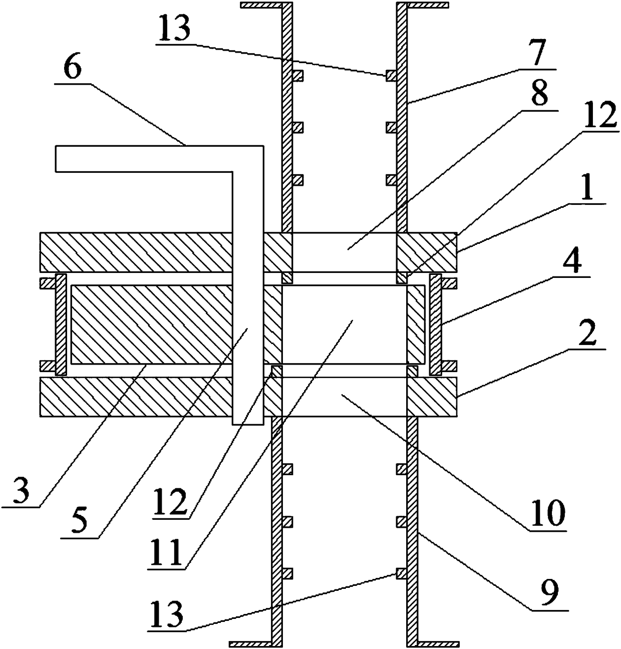
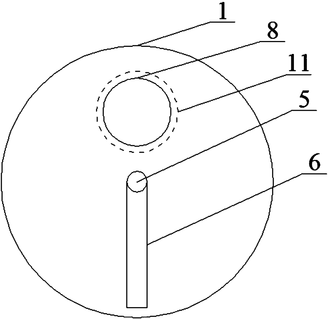
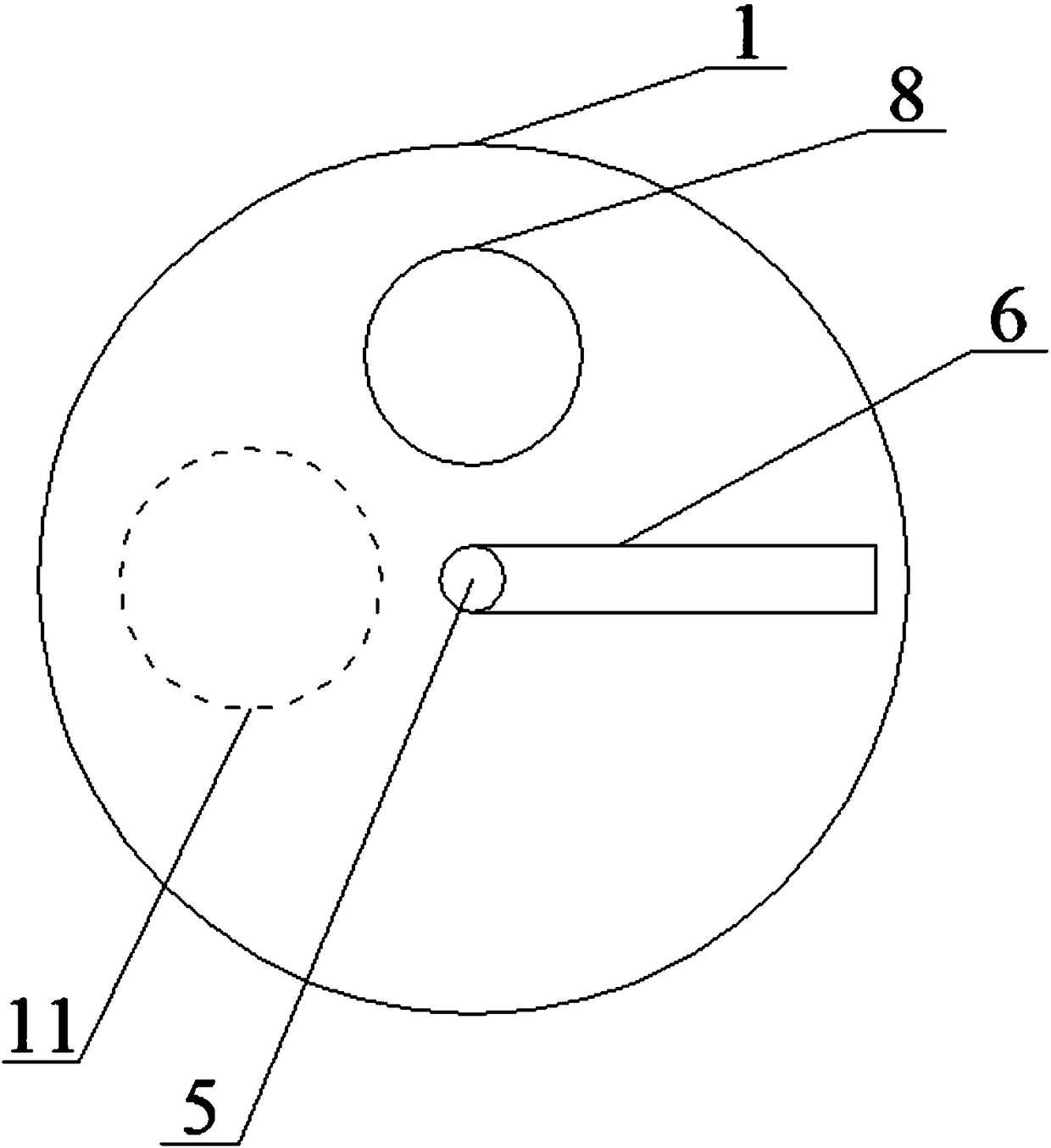
[0033] refer to figure 1 , in the first embodiment given in this paper, the anti-jamming and erosion-resistant material door includes an upper fixed valve plate 1, a lower fixed valve plate 2 and a rotating valve plate 3, and the rotating valve plate 3 is located between the upper fixed valve plate 1 and the lower fixed valve plate. Between the valve plates 2, all three are circular, concentric and parallel up and down. The radii of the upper fixed valve plate 1 and the lower fixed valve plate 2 are greater than the radius of the rotating valve plate 3, and a valve body 4 is arranged around the rotating valve plate 3, and the upper and lower sides of the valve body 4 are closely attached to the upper fixed valve plate 1 and the lower fixed valve plate respectively. The plate 2 protrudes from the part other than the rotating valve plate 3, so that the upper fixed valve plate 1, the lower fixed valve plate 2 and the valve body 4 surround the rotating valve plate 3. The turning ...


PUM


Abstract

The invention discloses an anti-clamping flushing-resistance material door. The anti-clamping flushing-resistance material door includes an upper fixed valve plate, a lower fixed valve plate and a rotating valve plate which can circumferentially rotate in a reciprocating mode. Through-flow holes are formed in the upper fixed valve plate, the lower fixed valve plate and the rotating valve plate, and the through-flow holes on the upper fixed valve plate and the lower fixed valve plate correspond to each other in the flowing direction and are separately used as a feeding inlet and a discharging outlet. Opening and closing of the material door are realized by rotating the rotating valve plate, specifically, when the rotating valve plate is rotated, the through-flow hole on the rotating valve plate shears the through-flow holes on the upper fixed valve plate and the lower fixed valve plate and gradually blocks and closes the material door; and when the rotating valve plate is rotated, the through-flow hole on the rotating valve plate gradually communicates with the through-flow holes on the upper fixed valve plate and the lower fixed valve plate to open the material door. A buffer partis arranged on the inner wall of a feeding pipe connected with the through-flow hole of the upper fixed valve plate. The invention further provides a use method of the anti-clamping flushing-resistance material door. Opening and closing of a material pipeline are realized through shearing action, the phenomenon of material clamping and clamping of the material door is avoided, and flushing of thematerial to the material door and the pipeline is further reduced through the buffer part.

Description

technical field [0001] The invention belongs to the technical field of valves, in particular to an anti-jamming and erosion-resistant material door and its use method. Background technique [0002] There are many types of valves used in pipelines for transporting gas and liquid, but for pipelines for transporting granular materials such as coal and mud, there are some shortcomings in the application of many existing types of valves. For example, for the butterfly valve type valve, when it is applied to the above-mentioned material pipeline, the phenomenon of stuffing is easy to occur due to the rotation of the valve disc during the sealing process, resulting in poor sealing effect and valve jamming, and due to the sealing structure principle of the butterfly valve itself Limitations - the disc is in the middle of the channel, so the minimum diameter of the butterfly valve is generally not less than DN50 (2 inches about 50mm). In addition, no matter it is a butterfly valve o...

Claims


Application Information

Patent Timeline
IPC IPC(8): F16K5/04F16K5/08F16K31/53
CPCF16K5/04F16K5/08F16K31/53
Inventor 潘健
Owner 潘健
Learn More