
A semiconductor light-emitting diode manufacturing equipment

A technology of light-emitting diodes and semiconductors, applied in semiconductor devices, electrical components, circuits, etc., can solve the problems of low safety, potential safety hazards, inconvenient assembly and replacement of rotary knives, etc., and achieve the effect of convenient operation and simple structure

Active Publication Date: 2019-02-15
广东安林电子科技股份有限公司
View PDF3 Cites 0 Cited by
  • Summary
  • Abstract
  • Description
  • Claims
  • Application Information

AI Technical Summary

Problems solved by technology

[0002] Semiconductor light-emitting diodes are commonly used electronic components at present. During the production and manufacturing process of semiconductor light-emitting diodes, it is often necessary to cut the raw materials of semiconductor light-emitting diodes. It is inconvenient to assemble and replace the rotary knife, which affects the normal use of the cutting facility, thereby reducing the working efficiency of the cutting facility. In addition, the cutting rotary knife of the existing cutting facility is exposed and has no protective measures, which is low in safety and has a large Potential safety hazards, affecting the production and manufacturing of semiconductor light-emitting diodes

Method used


Image

  • A semiconductor light-emitting diode manufacturing equipment
  • A semiconductor light-emitting diode manufacturing equipment
  • A semiconductor light-emitting diode manufacturing equipment

Examples


Embodiment Construction

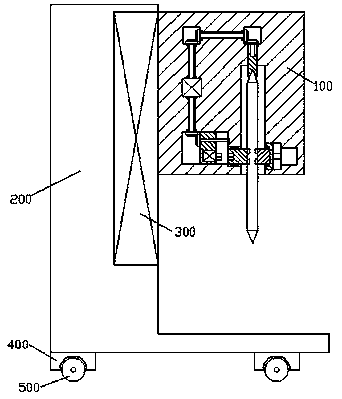
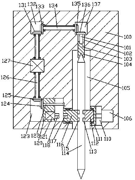
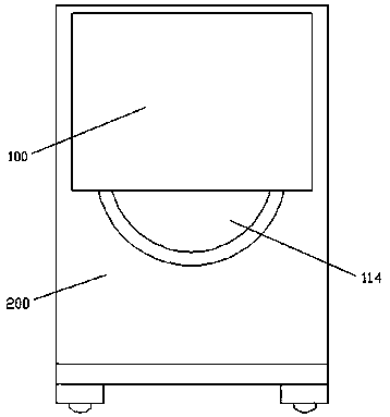
[0014] Combine below Figure 1-4 The present invention will be described in detail.

[0015] refer to Figure 1-4 According to an embodiment of the present invention, a semiconductor light-emitting diode manufacturing equipment includes a manufacturing frame body 100, the manufacturing frame body is installed on the right end surface of the support 200 through a lifting device 300, and the bottom end surface of the support 200 is fixed around A foot column 400 is provided, and a roller 500 is installed for rolling fit in the bottom end surface of the foot column 400, and a fitting cavity 105 is arranged in the bottom end surface of the manufacturing frame body 100, and a rotating knife is installed in the fitting cavity 105 for rotation fit. 114, the inner wall on the right side of the fitting cavity 105 is provided with a snap-fit ​​assembly for locking and fitting connection with the rotary knife 114, and the inner wall of the manufacturing frame 100 on the left side of the...


PUM


Abstract

The present invention discloses a novel semiconductor light emitting diode manufacturing device. The manufacturing device comprises a manufacturing rack body, the manufacturing rack body is installedat the end face of the right side of a support through a lifting device, legs are fixedly arranged at the periphery of the end face of the bottom portion of the support, rollers are in rolling fit installation in the end faces of the bottom portions of the legs, the end face of the bottom portion of the manufacturing rack body is internally provided with a mounting and combination cavity, a rotating blade is in rotation fit installation in the mounting and combination cavity, a clamping module being in locking fit connection with the rotating blade is arranged at the inner wall of the right side of the mounting and combination cavity, a slipping cavity is arranged in an inner wall body of the manufacturing wall body at the left side of the mounting and combination cavity, a left turning connection head is in rotation fit installation in a wall body between the slipping cavity and the mounting and combination cavity, a splined hole is internally provided with the end face of the left side of the left turning connection head, a slipping block is in slipping fit installation in the slipping cavity, a first motor is fixedly arranged in the end face of the right side of the slipping block, and a splined arm being in spline fit connection with the splined hole is in power fit installation with the right side end of the first motor.

Description

technical field [0001] The invention relates to the field of manufacturing electronic components, in particular to semiconductor light-emitting diode manufacturing equipment. Background technique [0002] Semiconductor light-emitting diodes are commonly used electronic components at present. During the production and manufacturing process of semiconductor light-emitting diodes, it is often necessary to cut the raw materials of semiconductor light-emitting diodes. It is inconvenient to assemble and replace the rotary knife, which affects the normal use of the cutting facility, thereby reducing the working efficiency of the cutting facility. In addition, the cutting rotary knife of the existing cutting facility is exposed and has no protective measures, which is low in safety and has a large Potential safety hazards affect the production of semiconductor light-emitting diodes. Contents of the invention [0003] The purpose of the present invention is to provide a semiconduc...

Claims


Application Information

Patent Timeline
Patent Type & Authority Patents(China)
IPC IPC(8): H01L33/00
CPCH01L33/005
Inventor 汪贤女
Owner 广东安林电子科技股份有限公司
Learn More