Electronic component

A technology of electronic components and recesses, applied to electrical components, parts of transformers/inductors, circuits, etc., can solve problems such as insufficient chip volume

Active Publication Date: 2018-08-28
TDK CORPARATION
View PDF6 Cites 0 Cited by
  • Summary
  • Abstract
  • Description
  • Claims
  • Application Information

AI Technical Summary

Problems solved by technology

Therefore, sometimes the capacity of the chip cannot be sufficiently secured

Method used


Image

  • Electronic component
  • Electronic component
  • Electronic component

Examples


Embodiment Construction

[0017] Embodiments will be described in detail below with reference to the drawings. In the description, the same symbols are used for the same elements or elements having the same functions, and overlapping descriptions are omitted.

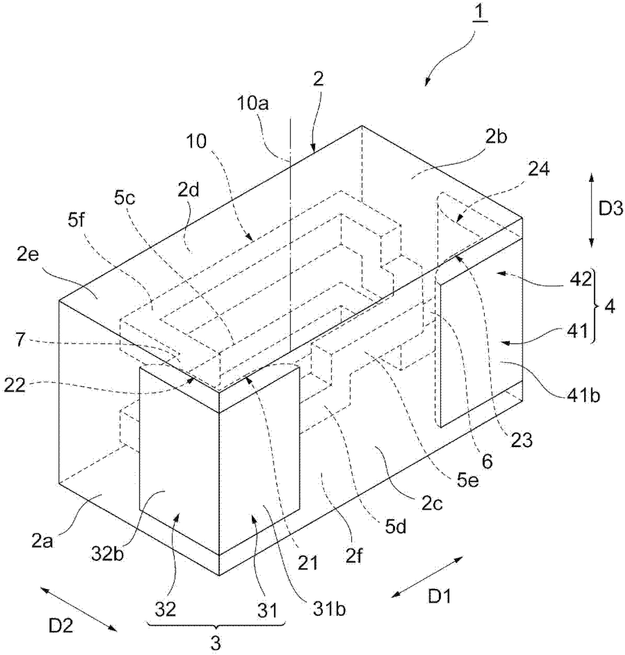
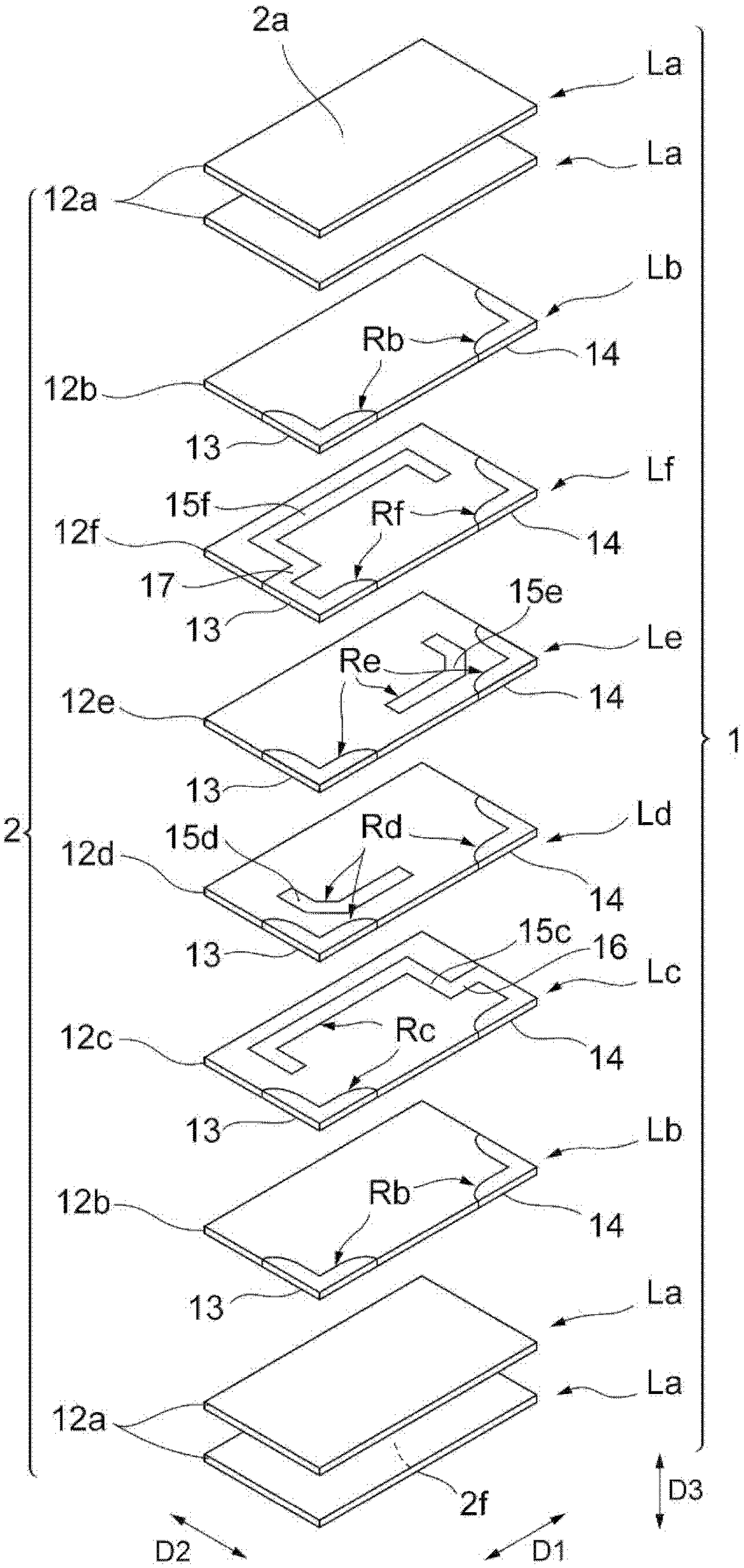
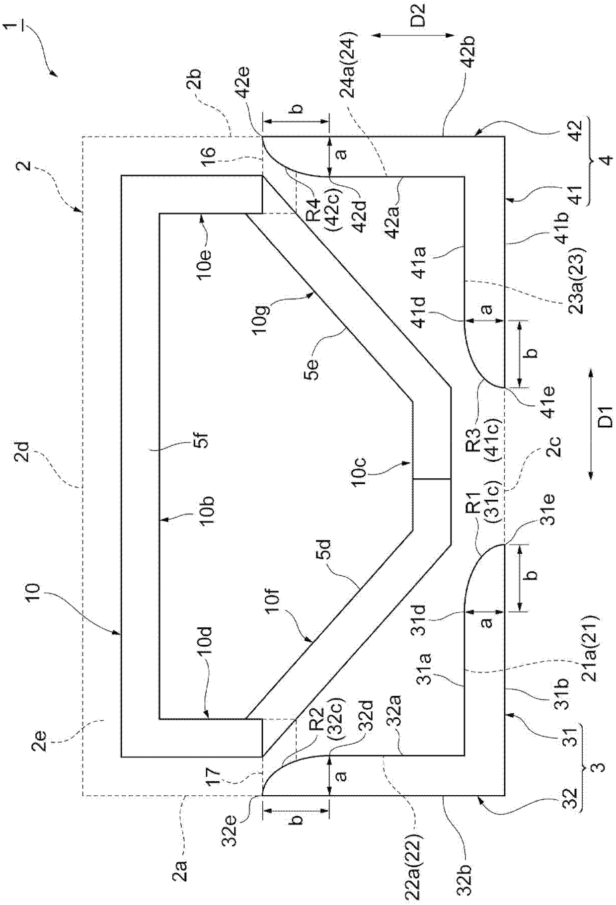
[0018] refer to Figure 1 ~ Figure 3 The laminated coil component of the embodiment will be described. figure 1 It is a perspective view of the laminated coil component of embodiment. figure 2 Yes figure 1 An exploded perspective view of the laminated coil assembly shown. image 3 yes means figure 1 A top view of the relationship between the coil and mounting conductor shown. image 3 It is a plan view of the laminated coil component 1 viewed from the side surface 2e, and the element body 2 and the connection conductors 6 and 7 are indicated by dotted lines.

[0019] like Figure 1 ~ Figure 3 As shown, the laminated coil component 1 of the embodiment includes an element body 2 , mounting conductors 3 , 4 , a plurality of coil conductors ...


PUM


Abstract

The invention relates to an electronic component. The electronic component includes an element provided with a first recess, and a mounting conductor including a first conductor portion disposed in the first recess. The first conductor portion has a first face opposed to a bottom face of the first recess, a second face opposed to the first face, and a third face connecting the first face and the second face. The third face has a region overlapping with the second face as viewed from an opposing direction of the bottom face of the first recess and the first face.

Description

technical field [0001] One aspect of the present invention relates to an electronic component. Background technique [0002] There is known an electronic component including a chip and a mounting conductor provided on the surface of the chip. In this electronic component, since the mounting conductors are formed on the outer surface of the chip, it is necessary to make the size of the chip slightly smaller than the predetermined size of the electronic component. Therefore, the capacity of the chip may not be sufficiently ensured. Therefore, Japanese Patent No. 4816971 discloses an electronic component including an element body and a mounting conductor arranged in a recess provided on the element body. In this electronic component, since the conductor for mounting is arranged in the concave portion, the volume of the element body can be ensured. Contents of the invention [0003] In the above-mentioned electronic components, cracks may occur in the element body. [0004...

Claims


Application Information

Patent Timeline
Patent Type & Authority Applications(China)
IPC IPC(8): H01F17/04
CPCH01F17/04H01F2017/0066H01F17/0013H01F27/292H01F41/04H01F27/323H01F27/28
Inventor 石间雄也松山靖志贺悠人青木俊二近藤真一
Owner TDK CORPARATION
Why Eureka
Try Eureka