Labyrinth seal device

A labyrinth seal and seal seat technology, which is applied in the direction of engine seals, engine components, mechanical equipment, etc., can solve the problems of labyrinth seals losing sealing effect, comb teeth colliding with the rotating shaft, and throttling tooth gap becoming larger, so as to reduce maintenance and replacement costs, guarantee the sealing effect, and prolong the service life

Inactive Publication Date: 2018-08-28
马鞍山市麦克英孚机械科技有限公司
View PDF6 Cites 0 Cited by
  • Summary
  • Abstract
  • Description
  • Claims
  • Application Information

AI Technical Summary

Problems solved by technology

However, for equipment with a long rotating shaft, in the process of starting and stopping, the rotating speed of the rotating shaft needs to pass through more than one critical speed during the change process. Near the critical speed, the vibration of the rotating shaft will increase sharply, making the comb Friction or even collision between the teeth and the rotating shaft causes the throttling tooth gap to become larger, and eventually the labyrinth seal loses its sealing effect due to the breakage of the comb teeth, and the replacement cost is high

Method used


Image

  • Labyrinth seal device
  • Labyrinth seal device
  • Labyrinth seal device

Examples


Embodiment Construction

[0021] The following will clearly and completely describe the technical solutions in the embodiments of the present invention with reference to the accompanying drawings in the embodiments of the present invention. Obviously, the described embodiments are only some, not all, embodiments of the present invention. All other embodiments obtained by persons of ordinary skill in the art based on the embodiments of the present invention belong to the protection scope of the present invention.

[0022] According to an embodiment of the present invention, a labyrinth sealing device is provided.

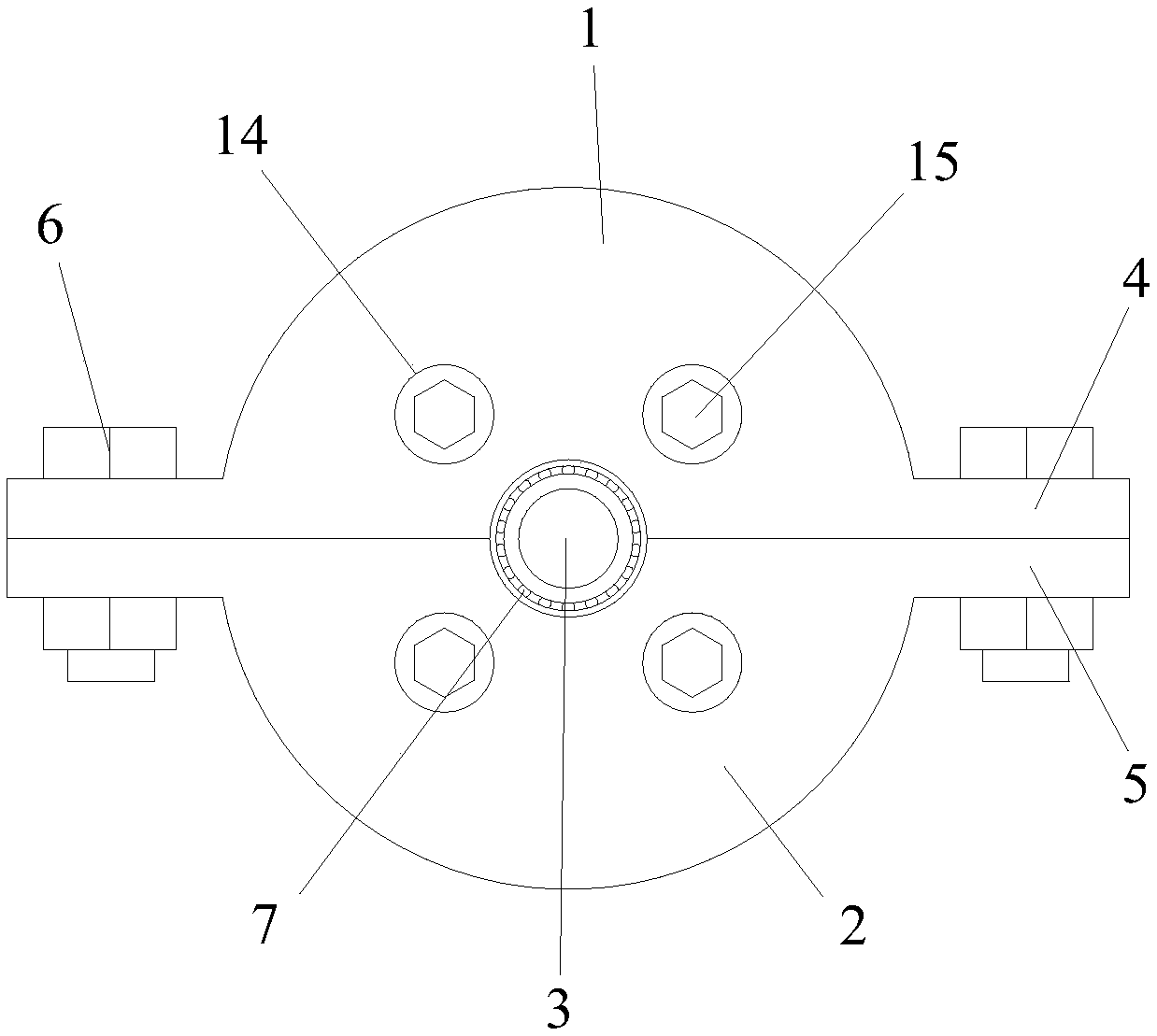
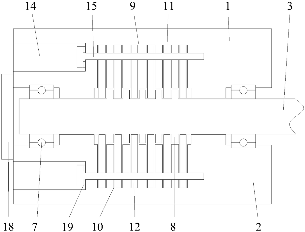
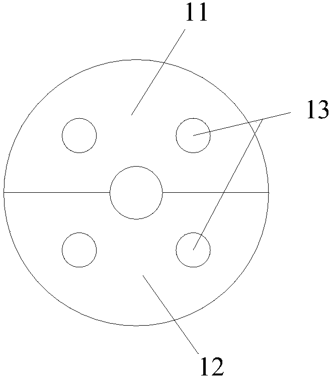
[0023] Such as Figure 1-5 As shown, the labyrinth sealing device according to the embodiment of the present invention includes an upper sealing seat 1, a lower sealing seat 2 and a rotating shaft 3, and upper fixing plates are respectively provided at the opposite ends of the upper sealing seat 1 and the lower sealing seat 2. 4 and the lower fixing plate 5, the upper fixing plate 4 and the ...


PUM


Abstract

The invention discloses a labyrinth seal device. The labyrinth seal device comprises an upper sealing base, a lower sealing base and a rotation shaft. The two ends of the opposite faces of the upper sealing base and the lower sealing base are provided with an upper fixing plate and a lower fixing plate correspondingly, and the upper fixing plate and the lower fixing plate are fixedly connected through bolts and nuts. The rotation shaft is movably connected to the middle portion between the upper sealing base and the lower sealing base. The side faces of the parts, located at the two ends of the upper sealing base and the two ends of the lower sealing base, of the rotation shaft are provided with bearings. Inner rings of the bearings are fixed to the side face of the rotation shaft. Outer rings of the bearings are fixed to the upper sealing base and the lower sealing base. The middle portion of the side face of the part, located between the bearings, of the rotation shaft is provided with a plurality of annular comb teeth, the positions, corresponding to the part between the annular comb teeth, in the upper sealing base and the lower sealing base are internally provided with an upper comb tooth groove and a lower comb tooth groove correspondingly. The upper comb tooth groove is internally provided with upper comb tooth sheets matched with the upper comb tooth groove, and the lower comb tooth groove is internally provided with lower comb tooth sheets matched with the lower comb tooth groove. The labyrinth seal device has the beneficial effects that it is guaranteed that the labyrinth seal section rotation shaft does not vibrate, constant comb tooth gaps are guaranteed, maintenance is convenient, and the replacement cost is low.

Description

technical field [0001] The invention relates to the technical field of labyrinth seals, in particular to a labyrinth seal device. Background technique [0002] Labyrinth seals are also called comb seals, which are non-contact seals. Mainly used to seal gaseous media, it is widely used as interstage seal, shaft end seal and blade tip seal, or front seal of other dynamic seals in steam turbines, gas turbines, centrifugal compressors, blowers and other machines. The leakage of the labyrinth seal is proportional to the size of the throttle backlash, the smaller the throttle backlash, the less the leakage of the labyrinth seal. However, for equipment with a long rotating shaft, in the process of starting and stopping, the rotating speed of the rotating shaft needs to pass through more than one critical speed during the change process. Near the critical speed, the vibration of the rotating shaft will increase sharply, making the comb The teeth rub against or even collide with th...

Claims


Application Information

Patent Timeline
Patent Type & Authority Applications(China)
IPC IPC(8): F16J15/447
CPCF16J15/447
Inventor 吴明星
Owner 马鞍山市麦克英孚机械科技有限公司
Why Eureka
Try Eureka