Cam sleeve power shaft-driven hollow cam sleeve impact box for implementing method for driving rotation of hollow cam sleeve by cam sleeve power shaft
A technology of cam sleeve and power shaft, which is applied in the direction of driving device, earth drilling, cutting machinery, etc., and can solve the problems of many wearing parts, broken structure, scrapping of reciprocating impact system, etc.
- Summary
- Abstract
- Description
- Claims
- Application Information
AI Technical Summary
Problems solved by technology
Method used
Image
Examples
Embodiment 1
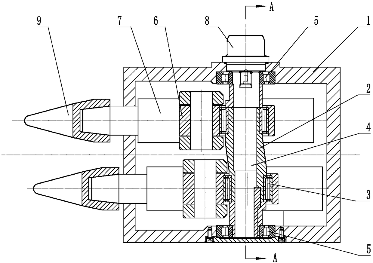
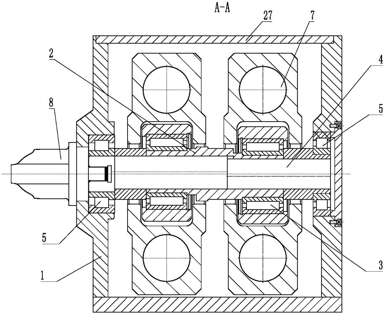
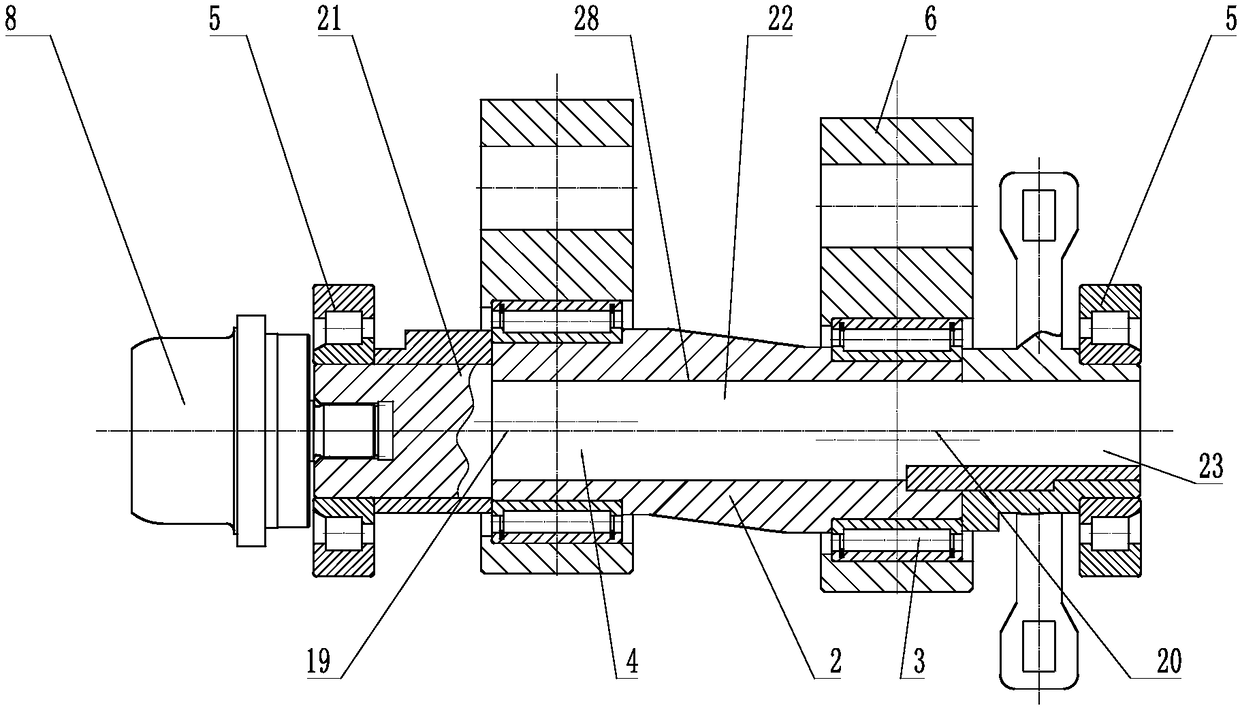
[0052] Such as Figure 1 to Figure 5As shown, the cam sleeve power shaft drives the hollow cam sleeve impact box which implements the method that the cam sleeve power shaft drives the hollow cam sleeve to rotate, including the impact box 1, the hollow cam sleeve 2, the hollow cam sleeve bearing 3, the cam sleeve power shaft 4, and the power shaft Bearing 5, connecting rod 6, guide 7, power source 8, impact head 9, etc., impact box 1 includes box bottom plate 10 and box side plate 11, etc., and box bottom plate 10 and box side plate 11 are fixedly connected. The plate 11 includes a left side box plate 12 and a right side box plate 13, etc. The left side box plate 12 is provided with a left support transmission bearing hole 14 supporting the cam sleeve power shaft 4 and the right side box plate 13 is provided with a support cam sleeve power shaft 4 The right support transmission bearing hole 15, the center of circle of the left support transmission bearing hole 14 and the right ...
Embodiment 2
[0066] Such as Figure 6 As shown, the shaft anti-cam sleeve rotation structure 24 adopts the spline anti-cam sleeve rotation structure 30, and the spline anti-cam sleeve rotation structure 30 can make the parts on the cam sleeve power shaft 4 and the cam sleeve power shaft 4 have better alignment. The transmission power is uniform and can bear a large load.
[0067] The shaft anti-cam sleeve rotation structure 24 can also be a pin anti-cam sleeve rotation structure, a groove anti-cam sleeve rotation structure, a key anti-cam sleeve rotation structure, a thread anti-cam sleeve rotation structure, a screw anti-cam sleeve rotation structure, an eccentric piece anti-cam sleeve Rotation structure, interference fit anti-cam sleeve rotation structure or tapered surface anti-cam sleeve rotation structure, etc.
[0068] All the other are with embodiment 1.
Embodiment 3
[0070] Such as Figure 7 As shown, the shaft anti-cam sleeve rotation structure 24 adopts the key anti-cam sleeve rotation structure 31, and can also be a pin anti-cam sleeve rotation structure, a groove anti-cam sleeve rotation structure, a thread anti-cam sleeve rotation structure, a screw anti-cam sleeve rotation structure, Eccentric member anti-cam rotation structure, interference fit anti-cam rotation structure or tapered surface anti-cam rotation structure, etc.
[0071] All the other are with embodiment 1.
PUM
 Abstract
Description
Claims
Application Information
 - R&D
- Intellectual Property
- Life Sciences
- Materials
- Tech Scout
- Unparalleled Data Quality
- Higher Quality Content
- 60% Fewer Hallucinations
Browse by: Latest US Patents, China's latest patents, Technical Efficacy Thesaurus, Application Domain, Technology Topic, Popular Technical Reports.
© 2025 PatSnap. All rights reserved.Legal|Privacy policy|Modern Slavery Act Transparency Statement|Sitemap|About US| Contact US: help@patsnap.com


