Perforating fastening equipment

A device and hole button technology, which is applied in metal processing and other directions, can solve the problems of increasing the fabric looseness at the punching place, reducing the fabric processing accuracy, and increasing the fabric conveying and processing path.

Active Publication Date: 2018-08-28
重庆安布伦斯科技有限公司
View PDF6 Cites 0 Cited by
  • Summary
  • Abstract
  • Description
  • Claims
  • Application Information

AI Technical Summary

Problems solved by technology

[0004] The fastening process of the buckle and the buckle cap is generally done after all the fabrics are punched, and then the fabric is placed in the installation mechanism with the buckle and the buckle cap for installation, and the buckle mechanism and the punching mechanism of the fabric are set separately In this process, the fabric needs to be transmitted for a long time, which will increase the probability of loosening the fabric at the perforated area, increase the transmission and processing path of the fabric, reduce the processing accuracy of the entire fabric, and prolong the processing cycle of the entire fabric

Method used


Image

  • Perforating fastening equipment
  • Perforating fastening equipment

Examples


Embodiment Construction

[0018] Further detailed explanation through specific implementation mode below:

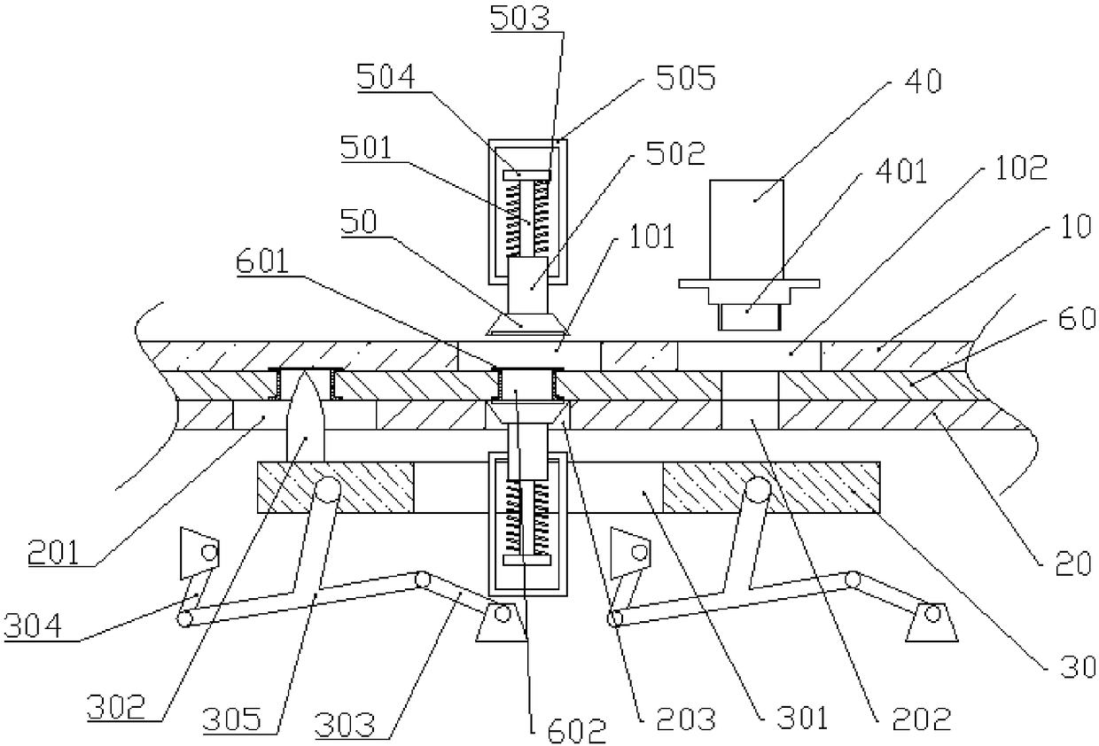
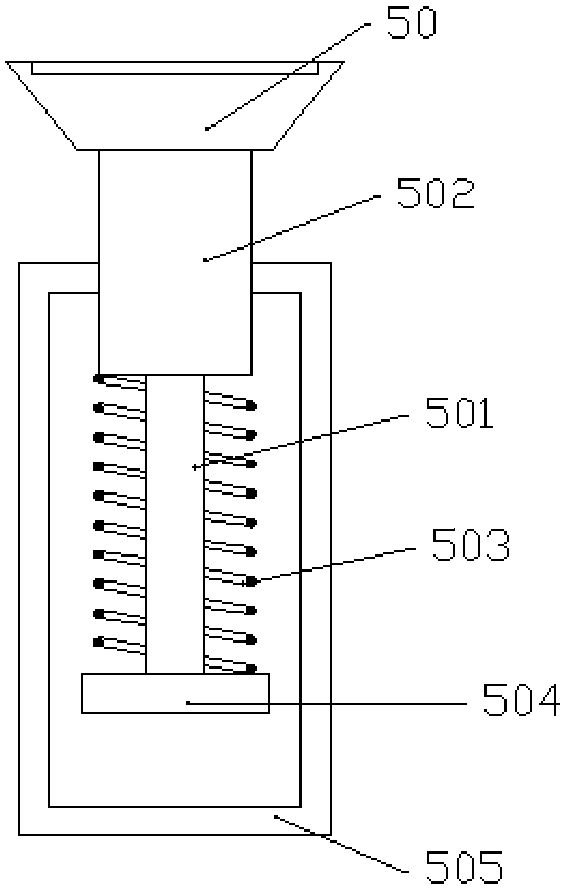
[0019] The reference signs in the accompanying drawings of the description include: the first limiting plate 10, the first mounting hole 101, the third through hole 102, the second limiting plate 20, the first through hole 201, the second through hole 202, the second Mounting hole 203, moving plate 30, fourth through hole 301, moving rod 302, first rocker 303, second rocker 304, swing rod 305, puncher 40, punching knife 401, suction cup 50, ejector rod 501 , Top block 502, stage clip 503, fixed block 504, pull bar 505, cloth 60, buckle cap 601, buckle 602.

[0020] The embodiment is basically as attached figure 1 And attached figure 2 Shown: punching and fastening equipment, including a transmission mechanism, a punching unit, two fastening mechanisms, and a first limiting plate 10 and a second limiting plate 20 arranged in sequence from top to bottom, the first limiting plate 10 A gap for pl...


PUM


Abstract

The invention relates to the field of perforating mounting and in particular discloses perforating fastening equipment. The perforating fastening equipment comprises a first limiting plate, a second limiting plate, a transfer mechanism, a perforating unit and two fastening mechanisms; the transfer mechanism comprises a moving plate, a moving rod and a transfer unit; the moving rod is located between the moving plate and the second limiting plate, and the lower end of the moving rod is fixedly connected to the upper surface of the upper surface of the moving plate, and a first through hole is formed in the second limiting plate; the perforating unit comprises a perforating machine and a perforating knife, the perforating machine is mounted above the first limiting plate, the perforating knife is vertically mounted on the lower surface of the perforating machine, a second through hole is formed in the second limiting plate, a third through hole where the perforating knife passes throughis formed in the first limiting plate, and the perforating knife, the third through hole and the second through hole are located in the same vertical axis; and the two fastening mechanisms are symmetrically arranged along the horizontal center line between the first limiting plate and the second limiting plate. According to the scheme, cloth can be perforated and fastened quickly.

Description

technical field [0001] The invention belongs to the field of punching and installation, and in particular relates to punching and fastening equipment. Background technique [0002] A common stretcher is a combination of metal pipe fittings and cloth, and the cloth is usually perforated for installation. During the installation process, the cloth covers the metal pipe fittings, and then the holes on the cloth are opposite to the holes, and then connected to the cloth. The holes can realize the tension and fixation of the fabric. [0003] Generally, a punching machine is used to punch holes in the fabric, and the fabric is also conveyed during the punching process. During the transmission process, the punched part and the cross-sectional state of the cloth will cause the fabric at the punched part to loosen easily, causing the cloth to be damaged; Generally, it is necessary to fasten the perforated part of the cloth with structures such as buckle rings and buckle caps to prev...

Claims


Application Information

Patent Timeline
IPC IPC(8): B26F1/16
CPCB26F1/16
Inventor 彭洪德曹建国
Owner 重庆安布伦斯科技有限公司
Why Eureka
Try Eureka