
Bearing ring small box detection system

A bearing ring and detection system technology, applied in sorting and other directions, can solve problems such as isolation of products that cannot be tested and untested products, inspection of non-conforming products, rework, and inability to perform traceability isolation, to ensure the detection cycle and automation. High-level, stable beat detection effect

Active Publication Date: 2018-08-28
JIANGSU YAAO PRECISION MASCH CO LTD
View PDF11 Cites 1 Cited by
  • Summary
  • Abstract
  • Description
  • Claims
  • Application Information

AI Technical Summary

Problems solved by technology

[0002] In the existing bearing ring inspection process, because it is an assembly line operation, during the inspection process, the newly processed bearing rings also continuously enter the tray, so it is impossible to separate the inspected products from the uninspected products. When unqualified products are detected, other products within the operation period of the unqualified product or in the production batch of the unqualified product cannot be separated in a targeted manner, and all unqualified products in the batch cannot be inspected. Inspection and rework, that is, traceability isolation cannot be carried out, resulting in a high scrap rate in subsequent processes, and in severe cases, unqualified products will flow to customers, resulting in mass inspection quality accidents, which reduces customer satisfaction and increases the cost of full inspection. Labor cost

Method used


Image

  • Bearing ring small box detection system
  • Bearing ring small box detection system
  • Bearing ring small box detection system

Examples


Embodiment Construction

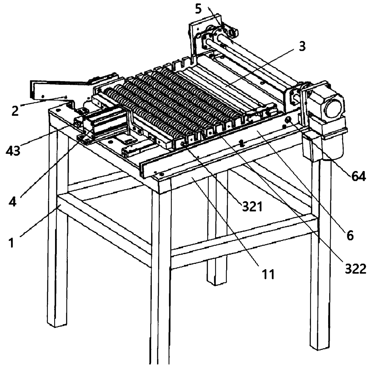
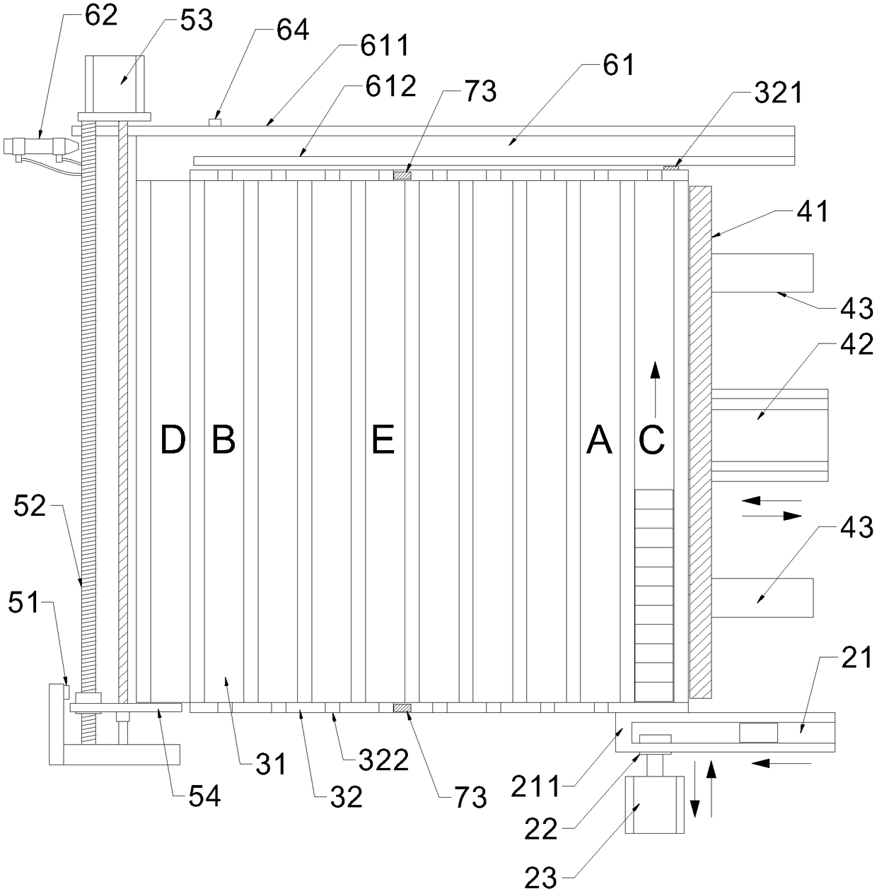
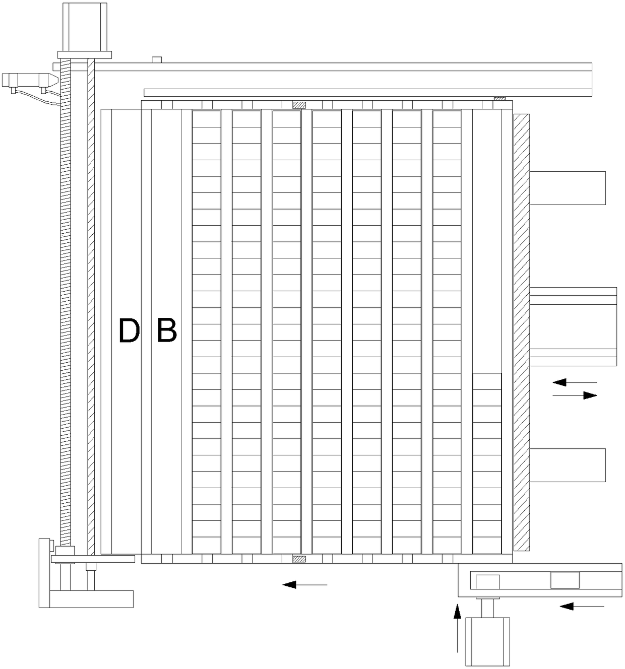
[0028] Such as Figure 1 to Figure 4 ,as well as Figure 6 As shown, a small box detection system for bearing rings includes a frame 1, a feeding mechanism 2, a material tray 3, an entire column pushing mechanism 4, a qualified product pushing mechanism 5, a discharging mechanism 6 and a control mechanism 7, The top of the frame 1 is provided with a material storage platform 11, the material tray 3 is arranged on the middle part of the material storage platform 11, the feeding mechanism 2 and the unloading mechanism 6 are arranged on the left and right sides of the material tray 3, and the whole row of pushing mechanism 4 and Qualified product pushing mechanism 5 is arranged on the front and rear sides of the tray 3, and the tray 3 is provided with a plurality of alignment grooves 31 for placing bearing rings and two baffle plates 32 arranged at both ends of the alignment groove 31. The first row of grooves 31 parallel to each other; feeding mechanism 2 and the first row of g...


PUM


Abstract

The invention provides a bearing ring small box detection system. The bearing ring small box detection system comprises a frame, a feeding mechanism, a charging tray, an alignment pushing mechanism, aqualified product pushing mechanism, a blanking mechanism and a control mechanism, wherein the feeding mechanism and the blanking mechanism are arranged on the left and right sides of the charging tray; the alignment pushing mechanism and the qualified product pushing mechanism are arranged on front and back sides of the charging tray; a plurality of alignment grooves are formed in the charging tray; the feeding mechanism is communicated with the first row of alignment grooves; the blanking mechanism is communicated with the last row of alignment grooves; spacer rods are arranged in the alignment grooves; a row of full-load inductors are arranged at the first row of alignment grooves in a baffle; the alignment pushing mechanism comprises an alignment pushing motor; the qualified product pushing mechanism comprises a photoelectric position sensor and a screw driving motor; the control mechanism comprises a controller and a touch screen; the row of full-load inductors and the photoelectric position sensor are connected with the controller; the controller is connected with the alignment pushing motor and the screw driving motor. By adopting the bearing ring small box detection system, unqualified products can be isolated in a tracing manner, and the rejection rate of products is lowered.

Description

technical field [0001] The invention belongs to the technical field of bearing ring production equipment, and in particular relates to a small-box detection system for bearing rings. Background technique [0002] In the existing bearing ring inspection process, because it is an assembly line operation, during the inspection process, the newly processed bearing rings also continuously enter the tray, so it is impossible to separate the inspected products from the uninspected products. When unqualified products are detected, other products within the operation time period of the unqualified product or other products in the production batch of the unqualified product cannot be separated in a targeted manner, and all unqualified products in the batch cannot be inspected. Inspection and rework, that is, traceability isolation cannot be carried out, resulting in a high scrap rate in subsequent processes. In severe cases, unqualified products will flow to customers and quality acci...

Claims


Application Information

Patent Timeline
Patent Type & Authority Applications(China)
IPC IPC(8): B07C5/00B07C5/02B07C5/36
CPCB07C5/00B07C5/02B07C5/362
Inventor 方国祥姚波方娅冯锦松王春蕾崔磊顾伟
Owner JIANGSU YAAO PRECISION MASCH CO LTD
Learn More