
Injection mold

A technology for injection molds and abrasive tools, applied in the field of injection molding equipment, can solve the problems of easily blocked exhaust groove exhaust, product surface trapped and scorched, product size instability, etc., to avoid local scorching, avoid scorching or The effect of lack of material and simple structure

Pending Publication Date: 2018-08-24
苏州精锐精密机械有限公司
View PDF0 Cites 2 Cited by
  • Summary
  • Abstract
  • Description
  • Claims
  • Application Information

AI Technical Summary

Problems solved by technology

[0003] A reasonable exhaust system can greatly reduce parameters such as injection pressure, injection time, holding time and clamping pressure, thereby improving production efficiency, reducing production costs, and reducing energy consumption of the machine; poor exhaust will lead to The compressed air immediately reaches a high temperature, which will cause local carbonization and burning of the part of the product in contact with the high-temperature air; and, in the injection molding process, if the gas cannot be discharged in time, it will be difficult to fill, resulting in product defects
[0004] The structure of the exhaust system of the traditional injection mold is to set the exhaust groove on the parting surface of the mold, and the exhaust groove cannot be made too deep or wide. Generally, the depth of the exhaust groove does not exceed 0.05mm, otherwise, the injection molding The raw material will flow into the exhaust groove, which will cause burrs and flashes and easily block the exhaust groove to affect the exhaust. However, when the injection molding raw material mixed with PPA and 50% glass fiber is injected, the injection temperature reaches 350°C, while the traditional injection molding Due to the limitation of the depth of the exhaust grooves, the number of the exhaust grooves, and the location of the mold, there is a problem of poor exhaust. Therefore, the temperature of the gas in the molding cavity is further increased after being heated by high temperature, resulting in the final product that is prone to surface defects. Defects such as trapped gas, charred, unstable product size, etc.

Method used


Image

  • Injection mold
  • Injection mold
  • Injection mold

Examples


Embodiment Construction

[0031] Objects, advantages and features of the present invention will be illustrated and explained by the following non-limiting description of preferred embodiments. These embodiments are only typical examples of applying the technical solutions of the present invention, and all technical solutions formed by adopting equivalent replacements or equivalent transformations fall within the protection scope of the present invention.

[0032] In the description of the scheme, it should be noted that the terms "center", "upper", "lower", "left", "right", "front", "rear", "vertical", "horizontal", " The orientation or positional relationship indicated by "inner", "outer", etc. is based on the orientation or positional relationship shown in the drawings, and is only for the convenience of description and simplification of description, rather than indicating or implying that the device or element referred to must have a specific orientation , constructed and operated in a particular or...


PUM


Abstract

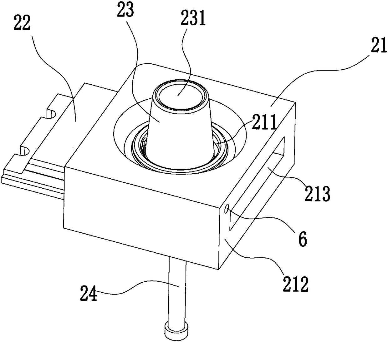
The invention discloses an injection mold. The injection mold comprises a first mold core and a second mold core which are matched to form a molding cavity; the second mold core comprises a body, twosliders and a shaping piece, and the body, the two sliders and the shaping piece can be combined into a local molding cavity; the two sliders can be inserted and connected into the body and can be spliced into a through hole coaxial with a center through hole in the body; the shaping piece can penetrate the center through hole and the through hole, and different areas of the peripheral wall of theshaping piece are attached to the inner walls of the center through hole and the through hole; and at least one exhausting channel communicating with the interior and the exterior of the molding cavity is formed on the two sliders. The scheme is ingenious in design and simple in structure, the second mold core is formed by joint cooperation of the body, the sliders and the shaping piece, exhausting channels are also added in cooperation gaps among the body, the sliders and the shaping piece, and exhausting is facilitated; and meanwhile the special-shaped exhausting channel is arranged on thesliders, it can be effectively achieved that gas in the molding cavity is fast discharged, the problem that scorching or incomplete filling occurs on a plurality of portions of a product is solved, and the product quality is guaranteed.

Description

technical field [0001] The present invention relates to injection molding equipment, especially injection molds. Background technique [0002] During the injection molding process, when the molten plastic enters the mold cavity, the air in the cavity needs to be drained instantly, including the air existing in the cavity and the gating system, and the water produced by the evaporation of the moisture contained in the injection molding raw materials at high temperature. Steam, gas generated by decomposition of injection molding materials at high temperature, gas generated by volatilization or chemical reactions of certain additives in injection molding materials, etc. [0003] A reasonable exhaust system can greatly reduce parameters such as injection pressure, injection time, holding time and clamping pressure, thereby improving production efficiency, reducing production costs, and reducing energy consumption of the machine; poor exhaust will lead to The compressed air imme...

Claims


Application Information

Patent Timeline
Patent Type & Authority Applications(China)
IPC IPC(8): B29C45/26B29C45/34B29C45/40B29C45/73B29C45/33
CPCB29C45/26B29C45/33B29C45/34B29C45/401B29C45/7312
Inventor 丁劲松孙念杰刘波
Owner 苏州精锐精密机械有限公司
Learn More