A method and device for implementing fault diagnosis

A fault diagnosis and network element technology, applied in digital transmission systems, data exchange networks, electrical components, etc., can solve problems such as increased maintenance costs, increased user maintenance time and cost, increased complexity, etc., to simplify the processing process and improve The effect of fault diagnosis efficiency

Active Publication Date: 2021-10-15
ZTE CORP
View PDF5 Cites 0 Cited by
  • Summary
  • Abstract
  • Description
  • Claims
  • Application Information

AI Technical Summary

Problems solved by technology

The following problems exist when implementing the above method: 1. The first node needs to know the TOP view of the entire network to determine the maximum value of TTL=X, which increases the complexity of Switch
2. The above process is usually triggered by the user on demand after the user sees the link connectivity alarm; if the user specifies the maximum value of TTL=X at the same time, the maintenance time and cost of the user will be increased
Especially in a network consisting of tens of thousands of nodes and tens of thousands of connections, on-demand maintenance will greatly increase the maintenance cost
3. When multiple links in the link fail at the same time, the above method cannot realize fault detection
[0005] To sum up, the method for fault diagnosis in related technologies is complex, and there are problems that maintenance and multi-segment link failures cannot be detected at the same time

Method used


Image

  • A method and device for implementing fault diagnosis
  • A method and device for implementing fault diagnosis
  • A method and device for implementing fault diagnosis

Examples


application example 1

[0166] The network element in this application example does not support the outbound packet delivery function and does not include the head and tail nodes according to the version number supported by the device (for example, the version number is less than 6). The application example is used to detect the connectivity of the LSP.

[0167] Figure 9 It is the method flowchart of the first application example of the present invention, as Figure 9 shown, including:

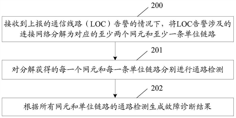
[0168] Step 900, the controller decomposes the connection network involved in the LOC alarm into at least two corresponding network elements and at least one unit link; including: the controller decomposes the unit link that needs path detection, and the unit link can be listed as a link list The unit link is composed of two adjacent NEs: the line between the network node interface (NNI) of the outgoing port of the westbound NE and the NNI of the incoming port of the eastbound NE. One network element, the first po...

application example 2

[0177] The network element in this application example is determined by the version number supported by the device (for example, the version number is less than 6) to determine the support for the packet delivery function of the outbound port. This application example connection includes the first and last nodes. The application example is used to detect the connectivity between VPWS CIPs .

[0178] Figure 11 It is a method flowchart of the second application example of the present invention, such as Figure 11 shown, including:

[0179] This application example controller receives a LOC alarm between VPWS CIPs.

[0180] Step 1100, the controller decomposes the connection network involved in the LOC alarm into at least two corresponding network elements and at least one unit link; including: the controller decomposes the unit link that needs path detection, and the unit link can be listed as a link list The unit link is composed of two adjacent NEs: the line between the ne...


PUM


Abstract

A method and device for implementing fault diagnosis, comprising: in the case of receiving a reported communication line (LOC) alarm, decomposing the connection network involved in the LOC alarm into at least two corresponding network elements and at least one unit link; Path detection is performed on each network element and unit link obtained through decomposition; fault diagnosis results are generated according to the path detection of all network elements and unit links. Wherein, the unit link is composed of two adjacent network elements: the line between the network node interface (NNI) of the outgoing port of the westbound network element and the NNI of the incoming port of the eastbound network element. The embodiment of the present invention simplifies the process of fault diagnosis and improves the efficiency of fault diagnosis.

Description

technical field [0001] This article involves but is not limited to software-defined network (SDN) technology, especially a method and device for implementing fault diagnosis. Background technique [0002] In a packet transport network (PTN, Packet Transport Network) network, the control plane and the forwarding plane are often implemented on a switching device (Switch). This implementation method determines the complexity of the switching device. On the other hand, the interface between the management plane and the switching device is defined privately by the manufacturer and is opaque. The interface left to the user is a black box without scalability. [0003] figure 1 It is a structural block diagram of an SDN network of related technologies, such as figure 1 As shown, in the SDN network, the control plane is separated from the switching device, and the switching device (Switch) is only responsible for data forwarding. The control plane consists of controllers. The co...

Claims


Application Information

Patent Timeline
Patent Type & Authority Patents(China)
IPC IPC(8): H04L12/24H04L12/26
CPCH04L41/0631H04L43/0811H04L43/08H04L41/0677H04L41/0604H04L41/40H04L43/20
Inventor 马西照李慧艳
Owner ZTE CORP
Why Eureka
Try Eureka