
Separate relay protection device

A relay protection device and separate technology, which is applied in the direction of emergency protection circuit devices, circuit devices, substation/distribution device shells, etc., can solve the problems of difficult transformation work, irregularities, and inconsistent protection configurations, and achieve replacement Short power outage time, improved replacement efficiency, flexible and convenient installation

Inactive Publication Date: 2018-08-21
SHANGHAI MUNICIPAL ELECTRIC POWER CO
View PDF5 Cites 2 Cited by
  • Summary
  • Abstract
  • Description
  • Claims
  • Application Information

AI Technical Summary

Problems solved by technology

However, there are still many engineering implementation problems in the renovation of old stations. For example, the devices of various manufacturers are quite different in terms of functional performance, size and structure, and external interfaces. The protection configuration is not uniform and standardized, and the requirements for external interfaces and circuit coordination are different. etc., increasing the difficulty of on-site engineering implementation
Due to the large difference in size, the existing standard relay protection devices in Shanghai cannot directly replace imported microcomputer protection devices. When replacing, the old devices need to be removed, and then holes are re-opened on the switch cabinet, which may affect other components on the panel. The normal use of the equipment, and the need to re-install the protection device and re-wiring during the transformation, directly lead to the difficulty of the transformation work and the long power outage time of the replacement work
Or adopt the scheme of replacing the switch cabinet door as a whole, but it takes a lot of time cost, labor cost and capital cost
Or develop a small-sized relay protection device, but this is a non-grid device, the size is not fully adaptable, the backplane needs to be rewired, and the cost is high

Method used


Image

  • Separate relay protection device
  • Separate relay protection device
  • Separate relay protection device

Examples


Embodiment Construction

[0018] In order to enable those skilled in the art to better understand the technical solution of the present invention, its specific implementation will be described in detail below in conjunction with the accompanying drawings:

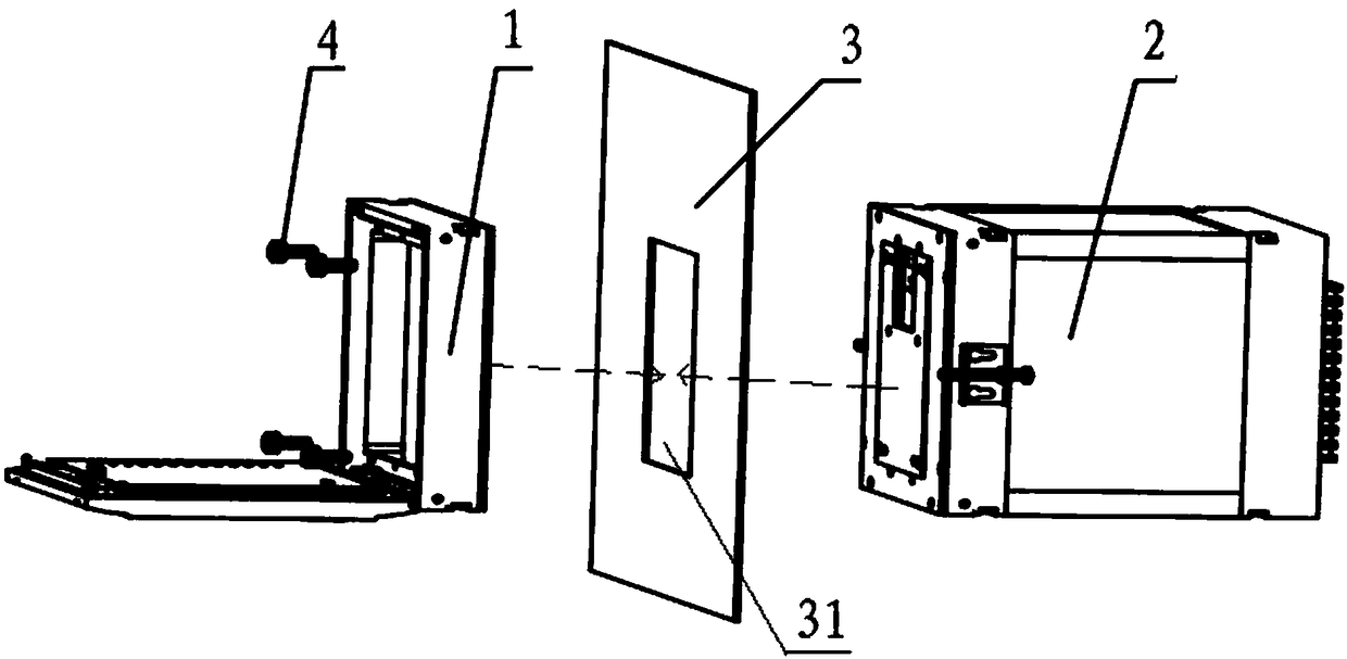
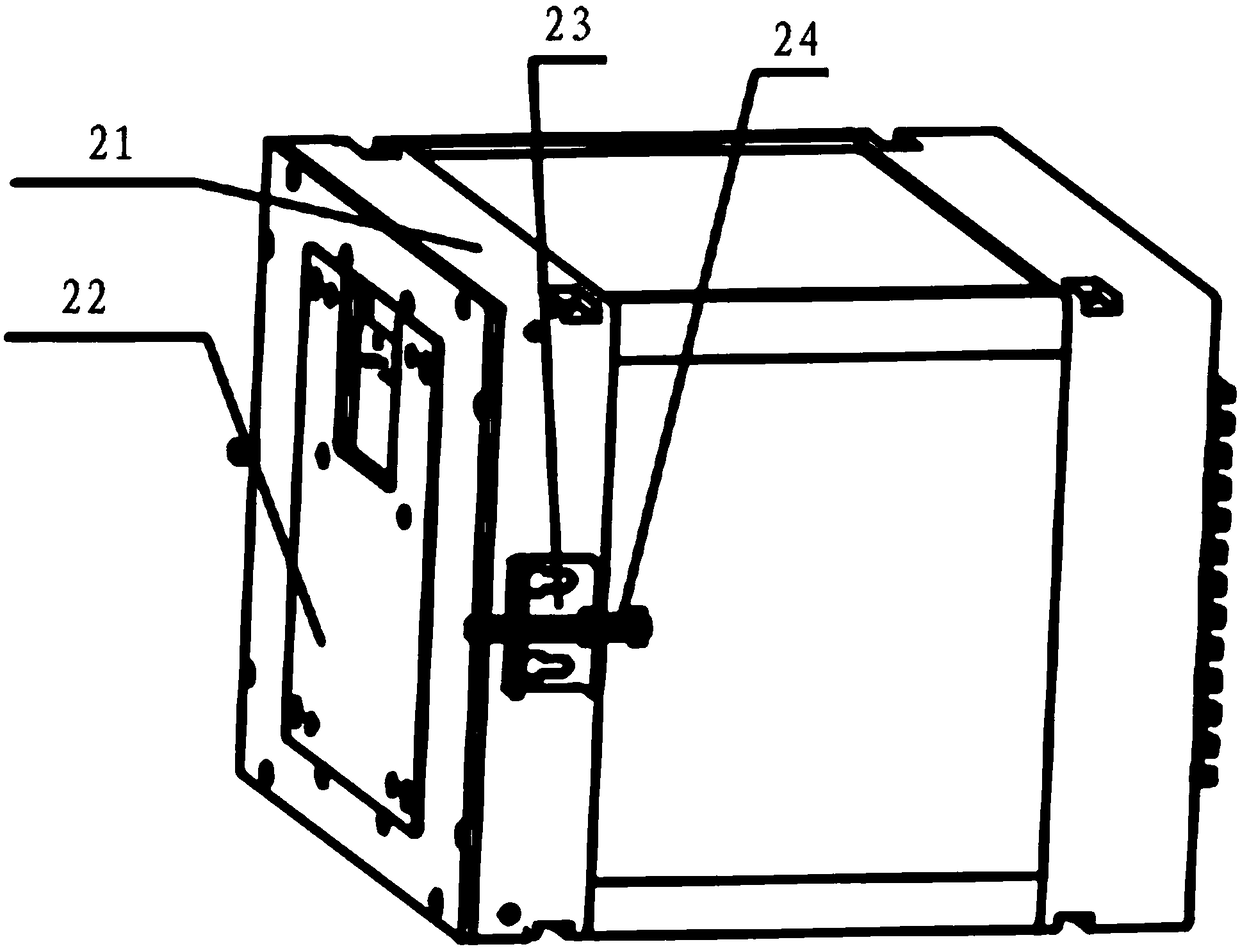
[0019] see figure 1 , figure 2 and image 3 , the best embodiment of the present invention, a separate relay protection device installed at the opening 31 of the switch cabinet door 3, the separate relay protection device includes a human-computer interaction module 1 and a box 2.

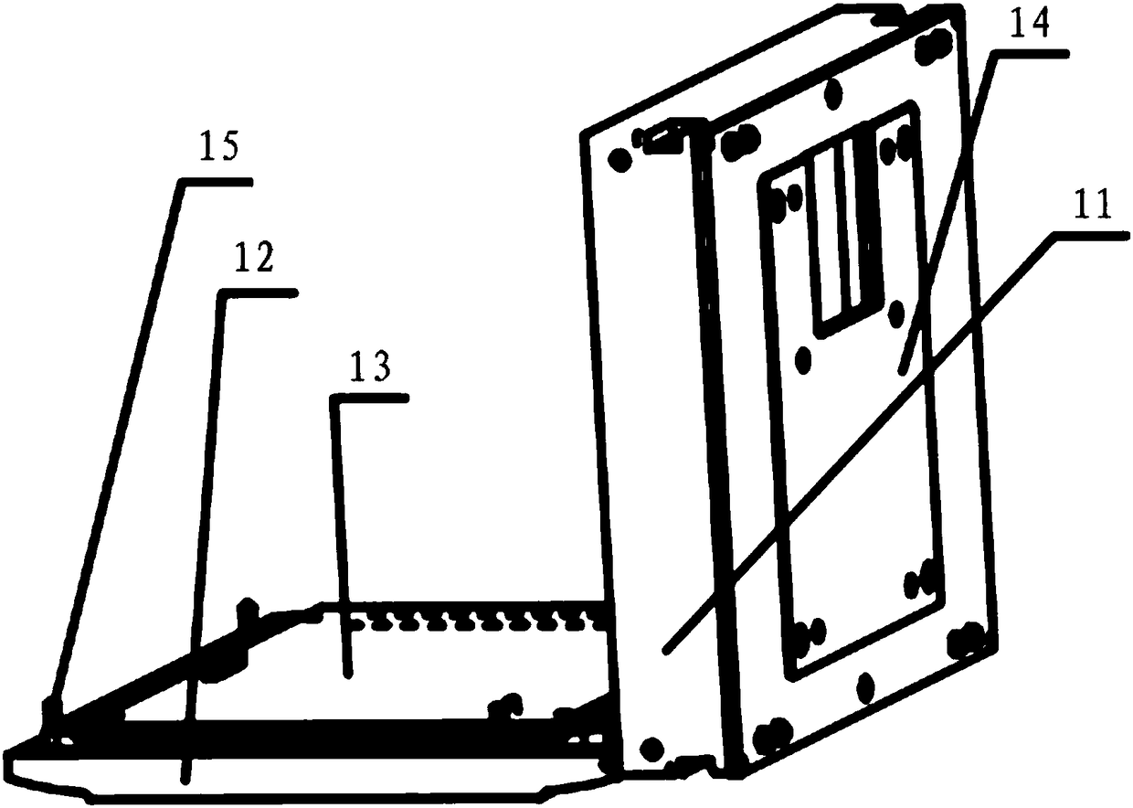
[0020] see again figure 2 , the human-computer interaction module 1 includes a front housing 11, a front panel 12, a liquid crystal panel 13 and a front limiting plate 14, the front housing 11 is a box structure with an open front end, and the front panel 12 is installed on the front housing by fixing screws 15 The front end of 11 is open, and the bottom end of front panel 12 and the bottom end of front casing 11 are hinged together, and front panel 12 can be opened...


PUM


Abstract

The invention discloses a separate relay protection device. The device comprises a human-machine interaction module and a box body. The human-machine interaction module comprises a front housing, a front panel, a liquid crystal plate and a front limiting plate; the box body comprises a rear housing and a rear limiting plate, the rear limiting plate is fixed to an outer wall face of a front panel of the rear housing, locking mechanisms are arranged on the left and right sides of the rear housing respectively, and locking screws are arranged on the locking mechanisms. The front limiting plate and the rear limiting plate are matched with an opening of a switch cabinet door separately; the front limiting plate is clamped to the front half portion of the interior of the opening of the switch cabinet door, the rear limiting plate is clamped to the rear half portion of the interior of the opening of the switch cabinet door, and the front housing, the front limiting plate, the switch cabinet door, the rear limiting plate and the rear housing are fixed together through multiple fastening screws. The separate relay protection device is flexible and convenient to install, and the power outagetime for replacement work is short.

Description

technical field [0001] The invention relates to a separate relay protection device. Background technique [0002] At present, various regions in China have gradually implemented some old substation renovation projects. In the process of transforming electromagnetic relays into microcomputer protection, and transforming conventional substations into smart substations, a certain amount of experience in substation transformation has been gradually accumulated. However, there are still many engineering implementation problems in the renovation of old stations. For example, the devices of various manufacturers are quite different in terms of function, performance, size and structure, and external interfaces. The protection configuration is not uniform and standardized, and the requirements for external interfaces and circuit coordination are different. etc., increasing the difficulty of on-site engineering implementation. Due to the big difference in size, the existing standardi...

Claims


Application Information

Patent Timeline
IPC IPC(8): H02H1/00H02B1/30
CPCH02H1/00H02B1/30
Inventor 陆昱龚越明朱洪成计杰徐能庄磊潘乐乐黄俊虞俊杰章家俊任昊吴奕姣
Owner SHANGHAI MUNICIPAL ELECTRIC POWER CO
Learn More