Waterproof heat dissipation structure of switch cabinet top plate

A technology of heat dissipation structure and cabinet top plate, which is applied to the cooling/ventilation of substation/switchgear, details of substation/switch layout, electrical components, etc., and can solve problems affecting the use of switchgear devices, easy leakage of switchgear, poor heat dissipation, etc. Achieve the effect of reasonable heat dissipation structure design, strong functionality, and not easy to enter water

Inactive Publication Date: 2018-08-21
FUZHOU ZHONGJILIAN ELECTROMECHANICAL TECH
View PDF0 Cites 0 Cited by
  • Summary
  • Abstract
  • Description
  • Claims
  • Application Information

AI Technical Summary

Problems solved by technology

[0003] 1. A large amount of heat is easy to accumulate on the roof of the existing switch cabinet, and it is not easy to discharge. If the temperature is too high, it will affect the use of the internal devices of the switch cabinet, and the heat dissipation is poor;
[0004] 2. Some switch cabinets also have cooling devices on the top plate, but the water resistance is poor, and the inside of the switch cabinet is prone to water leakage

Method used


Image

  • Waterproof heat dissipation structure of switch cabinet top plate
  • Waterproof heat dissipation structure of switch cabinet top plate
  • Waterproof heat dissipation structure of switch cabinet top plate

Examples


Embodiment Construction

[0020] The technical solutions in the embodiments of the present invention will be clearly and completely described below with reference to the accompanying drawings in the embodiments of the present invention. Obviously, the described embodiments are only a part of the embodiments of the present invention, but not all of the embodiments. Based on the embodiments of the present invention, all other embodiments obtained by those of ordinary skill in the art without creative efforts shall fall within the protection scope of the present invention.

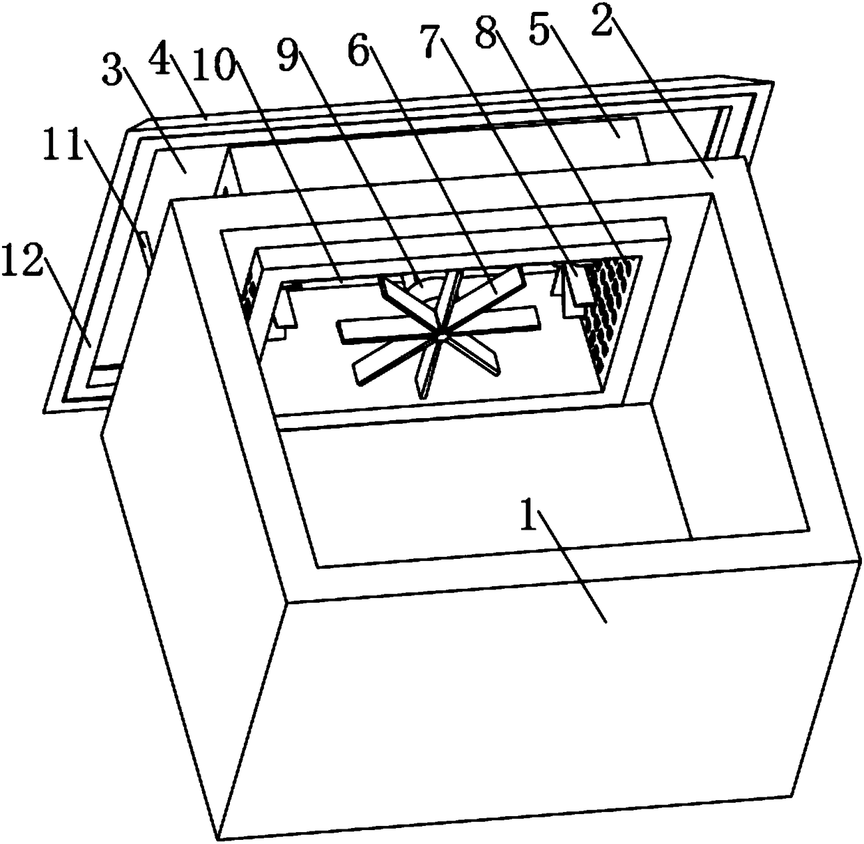
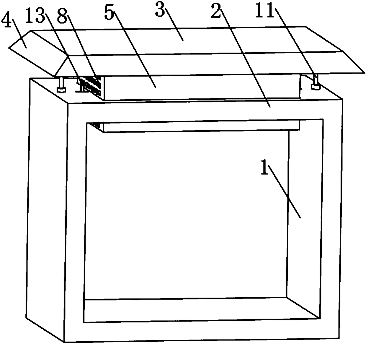
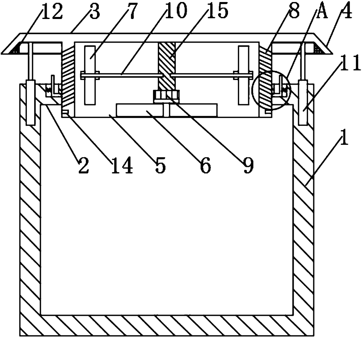
[0021] see Figure 1-4 , The present invention provides a technical solution: a waterproof heat dissipation structure for a switchgear top plate, comprising a switchgear body 1, a top plate 2, a rain shield 3 and a heat dissipation frame 5, the top of the switchgear body 1 is fixedly provided with a top plate 2, the top plate 2 is provided with a rain shield 3 above, the width and length of the rain shield 3 are respectively the same ...


PUM


Abstract

The invention discloses a waterproof heat dissipation structure of a switch cabinet top plate. The waterproof heat dissipation structure comprises a switch cabinet body, the top plate, a rain bafflingplate and a heat dissipation frame. The top plate is fixedly arranged on the top of the switch cabinet body, the rain baffling plate is arranged above the top plate, the width and length of the rainbaffling plate are consistent with the those of the top plate respectively, slanted rain baffling edges are fixedly arranged around the rain baffling plate, and rubber sealing pads are fixedly arranged on the lower surfaces of the rain baffling edges. According to the waterproof heat dissipation structure of the switch cabinet top plate, the heat dissipation performance of the top plate of the switch cabinet body is good, heat is not easily collected at the top plate, and the phenomenon cannot occur that devices in a switch cabinet are influenced during use since the temperature is too high; aheat dissipation structure on the top plate is reasonable in design, a heat dissipation effect is achieved, good waterproof performance is also achieved at the same time, water does not easily enterthe switch cabinet, the rain baffling plate can ascend and descend, and more convenience is provided for changing the heat dissipation amount of the top plate and the rain baffling degree according toactual needs. The waterproof heat dissipation structure is convenient to use and suitable for popularization.

Description

technical field [0001] The invention relates to the technical field of switch cabinets, in particular to a waterproof heat dissipation structure for a top plate of a switch cabinet. Background technique [0002] The switch cabinet is a kind of electrical equipment. The outside line of the switch cabinet first enters the main control switch in the cabinet, and then enters the sub-control switch. Each branch is set according to its needs. Such as instrumentation, automatic control, motor magnetic switch, various AC contactors, etc., and some also have high-voltage room and low-voltage room switch cabinets, high-voltage busbars, such as power plants, etc. load shedding, but this switchgear still has the following drawbacks in the actual use process: [0003] 1. A large amount of heat is easily accumulated at the top plate of the existing switch cabinet, and it is not easy to discharge. If the temperature is too high, it will affect the use of the internal devices of the switch...

Claims


Application Information

Patent Timeline
Patent Type & Authority Applications(China)
IPC IPC(8): H02B1/28H02B1/56
CPCH02B1/28H02B1/565
Inventor 洪灵峰
Owner FUZHOU ZHONGJILIAN ELECTROMECHANICAL TECH
Why Eureka
Try Eureka