
Shear box applicable to vertical ring-shear test

A shearing box and ring shearing technology, applied in the field of shearing box, can solve the problems of reduced precision of shearing force, inconsistent shearing displacement, inconsistent distribution of shearing line speed, etc., achieve convenient and fast operation process, and improve operation stability , Reduce the effect of frictional heat generation

Active Publication Date: 2018-08-21
CHINA UNIV OF GEOSCIENCES (WUHAN)
View PDF5 Cites 6 Cited by
  • Summary
  • Abstract
  • Description
  • Claims
  • Application Information

AI Technical Summary

Problems solved by technology

[0005] However, there is an inherent defect in the existing ring shear instruments: since the shear surface is a ring with a certain width in the radial direction, the shear line velocity distribution along the radial direction on the shear surface will be inconsistent. The inconsistency of the shear displacement in the shearing process will make the distribution of shear stress and shear displacement on the shearing surface uneven during the shearing process, so that the shearing process cannot restore the actual situation
However, there are many problems in the shear box in the currently disclosed vertical shear surface ring shear instrument, for example, the working process of the torque applying device is too cumbersome, and the shear rate during the test cannot be controlled, resulting in the The accuracy of the shear force on the sample is reduced, which affects the accuracy of the test results; sample preparation requires additional special equipment; The body cannot be tested with the ring shear instrument

Method used


Image

  • Shear box applicable to vertical ring-shear test
  • Shear box applicable to vertical ring-shear test
  • Shear box applicable to vertical ring-shear test

Examples


Embodiment Construction

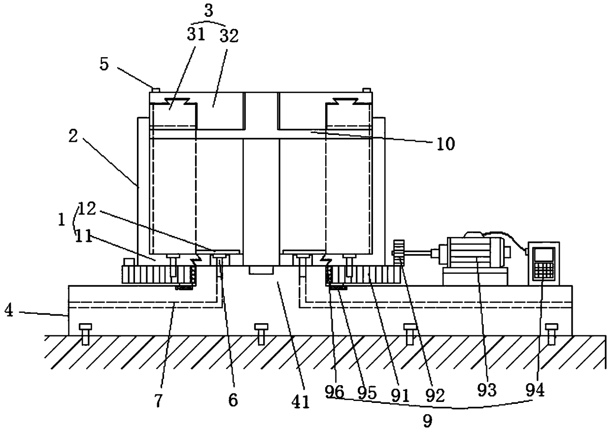
[0029] In order to make the purpose, technical solution and advantages of the present invention clearer, the embodiments of the present invention will be further described below in conjunction with the accompanying drawings.

[0030] Please refer to figure 1 , the embodiment of the present invention provides a kind of shear box that is suitable for vertical ring shear test, comprises bottom plate 1, outer cover 2, top cover 3 and top cover fixing bar 10, reserves a cylindrical hole in the middle of shear box, When the instrument is not in use, the top cover fixing rod 10 is installed in the cylindrical hole. When the test is carried out, the top cover fixing rod 10 is taken out and the normal stress loading device is installed.

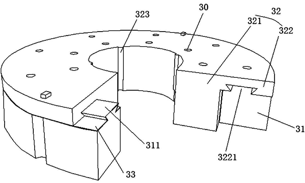
[0031] Please refer to figure 1 , 2and 4, the bottom plate 1 includes an outer bottom plate 11 and an inner bottom plate 12 that are slidably mounted together, the outer bottom plate 11 can rotate in a circular direction, and the circular rotation o...


PUM


Abstract

The invention discloses a shear box applicable to a vertical ring-shear test. The shear box comprises a bottom plate, an outer cover and a top lid, wherein the bottom plate comprises an outer bottom plate and an inner bottom plate which are glidingly mounted together, the inner bottom plate is fixed, the outer bottom plate can annularly rotate, soil sample fixing blades are arranged on the inner bottom plate, shear plates are arranged on the outer bottom plate, the outer bottom plate and the lower end of the outer cover are fixed together, vertical guide rails are arranged in the outer cover,and the vertical guide rails and the shear plates are staggered in position; the top lid comprises an outer top lid and an inner top lid which are glidingly mounted together, vertical guide slots matched with the vertical guide rails are formed in the outer wall of the outer top lid, and shear plate grooves matched with the shear plates are formed in the bottom of the outer top lid. The shearing process of a rock-soil body under the vertical ring-shear action can be realized, shear displacement and uniform distribution of shear stress at the shearing surface are guaranteed, two functions of sample preparation and testing can be considered, shearing force is provided through a stepless speed changing motor, and the testing accuracy is improved.

Description

technical field [0001] The invention relates to the technical field of geotechnical test equipment, in particular to a shear box suitable for vertical ring shear tests. Background technique [0002] The study of the shear strength characteristics of soil is of great significance for the analysis of slope stability, the study of the mechanical mechanism of geological disasters and the study of the progressive failure process of slopes. [0003] The shear strength characteristics of rock and soil can generally be obtained by in-situ tests or indoor geotechnical tests. The shear test has the disadvantages of high cost, long period, and heavy equipment. Compared with this, although the representativeness of soil samples is poor, the indoor test is more widely used in the study of the shear strength characteristics of soil due to its low cost, short period, and low price. [0004] At present, the commonly used devices for measuring the shear strength of soil all measure several...

Claims


Application Information

Patent Timeline
Patent Type & Authority Applications(China)
IPC IPC(8): G01N3/24G01N3/02
Inventor 宁奕冰唐辉明蔡毅范志强张俊荣申培武何成安鹏举
Owner CHINA UNIV OF GEOSCIENCES (WUHAN)
Learn More