Power takeoff control system with clutch and using method of power takeoff control system

A control system with clutch technology, applied in clutches, fluid-driven clutches, non-mechanical drive clutches, etc., can solve problems such as the inability to realize free shifting, and achieve the effects of avoiding parking, high safety, and avoiding operating errors

Active Publication Date: 2018-08-21
DONGFENG COMML VEHICLE CO LTD
View PDF5 Cites 3 Cited by
  • Summary
  • Abstract
  • Description
  • Claims
  • Application Information

AI Technical Summary

Problems solved by technology

[0005] The purpose of the present invention is to overcome the defects and problems existing in the prior art that free shifting cannot be realized under driving power taking conditions, and to provide a power taking off with clutch that can realize free shifting under driving power taking conditions. Controller control system and method of use thereof

Method used


Image

  • Power takeoff control system with clutch and using method of power takeoff control system

Examples


Embodiment 1

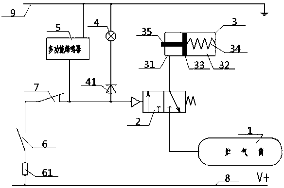
[0041] see figure 1 , a power take-off control system with a clutch, including a power take-off, a power take-off solenoid valve 2, a clutch, a clutch switch 7, a power take-off switch 6 and an air storage tank 1, the air outlet of the air storage tank 1 and the power take-off electromagnetic The air inlet of the valve 2 communicates, and the clutch cylinder 3 in the clutch includes an outer chamber 31, an inner chamber 32 and a clutch piston 33 between them, one side of the clutch piston 33 is connected to the inner chamber via a clutch spring 34. The right side wall of the chamber 32 is connected, and the other side of the clutch piston 33 is connected with one end of the connecting shaft 35, and the other end of the connecting shaft 35 extends outside the outer chamber 31, and is connected with the input end of the power take-off. Drive connection; the outer chamber 31 is connected to the air storage tank 1 through the power take-off solenoid valve 2, and the control end of...

Embodiment 2

[0044] Basic content is the same as embodiment 1, the difference is:

[0045] The junction between the clutch switch 7 and the control end of the power take-off solenoid valve 2 is connected to the ground wire 9 via the multifunctional buzzer 5 . The junction between the clutch switch 7 and the control end of the power take-off solenoid valve 2 is connected to the positive pole of the diode 41, and the negative pole of the diode 41 is connected to the ground wire 9 through the indicator light 4 of the instrument. The indicator light 4 is connected in parallel with the multifunctional buzzer 5 together.

[0046] When the power is taken normally, the multifunctional buzzer 5 and the indicator light 4 are energized, the multifunctional buzzer 5 makes a sound, and the indicator light 4 lights up to remind the operator that it is currently taking power. In addition, the diode Only one-way current flows through 41 to prevent the power take-off from malfunctioning; when the power ta...


PUM


Abstract

A power takeoff control system with a clutch comprises a power takeoff, the clutch, a clutch switch, a power takeoff switch, a power takeoff solenoid valve and a gas storage barrel, wherein the gas storage barrel communicates with a clutch cylinder via the power takeoff solenoid valve; a connecting shaft in the clutch cylinder is in driving connection with the power takeoff; a control end of the power takeoff solenoid valve is in circuit connection with a power wire via the clutch switch and the power takeoff switch successively; and a multifunctional buzzer and an instrument indicator lamp are in parallel connection between a ground wire and a junction between the clutch switch and the power takeoff solenoid valve, in use of the power takeoff control system, the clutch switch is used forcontrolling whether the power takeoff solenoid valve is electrified or not, therefore, whether the clutch cylinder is fed with gas or not is controlled, and then whether the power takeoff acts or notis controlled. By the design, free gear shifting under the working condition of running power takeoff can be realized, moreover, the prompting effect is good, and the safety is high.

Description

technical field [0001] The invention relates to a control system for a power take-off, in particular to a control system for a power take-off with a clutch and a method for using the same, and is particularly suitable for realizing free gear shifting under power take-off conditions while driving. Background technique [0002] The power take-off of the main box of the existing commercial vehicle gearbox takes power from the intermediate shaft of the gearbox, and the transmission route of the power take-off is the engine, the clutch, the first shaft of the transmission, the intermediate shaft of the transmission, and the power take-off is output through the flange or the spline. Under driving power take-off conditions (such as sprinklers, washing and sweeping vehicles), when the power take-off is working, the load always acts on the first shaft of the transmission. At this time, it is impossible to shift gears. The driver can only stop repeatedly - turn off the power take-off -...

Claims


Application Information

Patent Timeline
Patent Type & Authority Applications(China)
IPC IPC(8): B60K25/06B60Q9/00F16D25/12F16D25/0638
CPCF16D25/0638F16D25/14B60K25/06B60Q9/00F16D2025/081B60K2370/161
Inventor 蔚连浩杨帆赵晶张常武王超叶婷何秀校王峰张凯丽
Owner DONGFENG COMML VEHICLE CO LTD
Why Eureka
Try Eureka