Power takeoff relay control system with clutch and use method thereof

A relay-controlled technology with a clutch, applied in clutches, fluid-driven clutches, non-mechanical-driven clutches, etc., can solve problems such as the inability to achieve free shifting, and achieve the effect of good prompting effect, high safety, and avoiding operation errors.

Active Publication Date: 2018-09-28
DONGFENG COMML VEHICLE CO LTD
View PDF12 Cites 0 Cited by
  • Summary
  • Abstract
  • Description
  • Claims
  • Application Information

AI Technical Summary

Problems solved by technology

[0005] The purpose of the present invention is to overcome the defects and problems existing in the prior art that free shifting cannot be realized under driving power taking conditions, and to provide a power taking off with clutch that can realize free shifting under driving power taking conditions. Device relay control system and method of use thereof

Method used


Image

  • Power takeoff relay control system with clutch and use method thereof

Examples


Embodiment 1

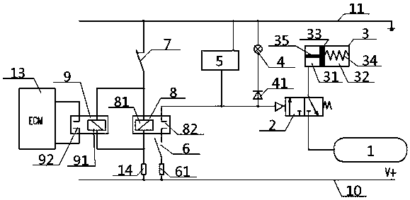
[0039] A relay control system for a power take-off with a clutch, comprising a clutch, a power take-off, a power take-off solenoid valve 2, an air storage tank 1, a clutch switch 7, a power take-off switch 6 and an internal relay 8, the air outlet of the air storage tank 1 It communicates with the intake port of the power take-off solenoid valve 2. The clutch cylinder 3 in the clutch includes an outer chamber 31, an inner chamber 32 and a clutch piston 33 between the two. One side of the clutch piston 33 is clutched. The spring 34 is connected with the right side wall of the inner chamber 32, the other side of the clutch piston 33 is connected with one end of the connecting shaft 35, the other end of the connecting shaft 35 extends outside the outer chamber 31, and is connected with the power take-off The input terminal of the power take-off solenoid valve 2 is connected for driving; the outer chamber 31 is connected to the gas tank 1 through the power take-off solenoid valve 2...

Embodiment 2

[0042] Basic content is the same as embodiment 1, the difference is:

[0043] The power take-off switch 6 is electrically connected with the power line 10 through the insurance 61, and the power line 10 is connected with the inner coil 81 through the load resistance 14.

Embodiment 3

[0045] Basic content is the same as embodiment 1, the difference is:

[0046] The power take-off relay control system also includes an external relay 9 and ECM13, the two ends of the ECM13 are connected to the two ends of the external contact 92 of the external relay 9, and one end of the external coil 91 in the external relay 9 is connected to the clutch switch 7, The junction of the inner coil 81 is connected, and the other end of the outer coil 91 is connected with the junction of the inner coil 81 and the power line 10 .

[0047] When the clutch switch 7 is closed, the external relay 9 is energized, and the external coil 91 and the external contact 92 are in contact with each other to send the signal that the clutch switch 7 is closed to the ECM13; when the clutch switch 7 is opened, the external relay 9 loses power, The outer coil 91 and the outer contact 92 are separated, and the ECM 13 cannot receive the signal from the outer relay 9, thereby judging that the clutch swi...


PUM


Abstract

The invention provides a power takeoff relay control system with a clutch. The power takeoff relay control system comprises an internal relay, a power takeoff, the clutch, a clutch switch, a power takeoff switch, a power takeoff solenoid valve and an air reservoir. The air reservoir communicates with a clutch air cylinder through the power takeoff solenoid valve, and a connecting shaft arranged inthe clutch air cylinder is connected with the power takeoff in a driving mode. The control end of the power takeoff solenoid valve sequentially passes through an inner contact and the power takeoff switch and then is connected with a power line in an electrical mode. An inner coil and the clutch switch connected in series are located between a grounding wire and the power line. A multi-function buzzer and a meter indicator lamp are connected in parallel between the joint of the inner contact and the power takeoff solenoid valve and the grounding wire. During use, the clutch switch controls whether the power takeoff solenoid valve is energized or not by the internal relay, thereby controlling whether the clutch air cylinder is inflated or not, and then whether the power takeoff acts or notis controlled. The power takeoff relay control system can not only realize free shifting of a driving car under the power takeoff working condition, but also has high prompting property, high safety,high sensitivity and good control effect.

Description

technical field [0001] The invention relates to a control system of a power take-off, in particular to a relay control system of a power take-off with a clutch and a method for using the same, and is particularly suitable for realizing free gear shifting under the power take-off working condition of a vehicle. Background technique [0002] The power take-off of the main box of the existing commercial vehicle gearbox takes power from the intermediate shaft of the gearbox, and the transmission route of the power take-off is the engine, the clutch, the first shaft of the transmission, the intermediate shaft of the transmission, and the power take-off is output through the flange or the spline. Under driving power take-off conditions (such as sprinklers, washing and sweeping vehicles), when the power take-off is working, the load always acts on the first shaft of the transmission. At this time, it is impossible to shift gears. The driver can only stop repeatedly - turn off the po...

Claims


Application Information

Patent Timeline
Patent Type & Authority Applications(China)
IPC IPC(8): B60K25/06B60Q9/00F16D25/12F16D25/0638
CPCF16D25/0638F16D25/12B60K25/06B60Q9/00
Inventor 蔚连浩王天奇杨帆赵晶李朝富敬丹青汤用廖宜剑张叶青
Owner DONGFENG COMML VEHICLE CO LTD
Why Eureka
Try Eureka