Tool for preventing flywheel of rear power take-off engine from rotation

A technology of engine and flywheel, which is applied in the direction of manufacturing tools, metal processing, metal processing equipment, etc., can solve the problems of damage to the flywheel shell E flywheel ring gear, etc., and achieve the goal of not easy to loosen, ensure power and starting performance, and improve rotation effect of effect

Pending Publication Date: 2018-08-21
GUANGXI YUCHAI MASCH CO LTD
View PDF0 Cites 0 Cited by
  • Summary
  • Abstract
  • Description
  • Claims
  • Application Information

AI Technical Summary

Problems solved by technology

In this way, when the flywheel bolt B is tightened or removed, the frock bolt D will collide and rub against the mounting hole of the flywheel housing E and the flywheel ring gear, which may damage the flywheel housing E and the flywheel ring gear

Method used


Image

  • Tool for preventing flywheel of rear power take-off engine from rotation
  • Tool for preventing flywheel of rear power take-off engine from rotation
  • Tool for preventing flywheel of rear power take-off engine from rotation

Examples


Embodiment Construction

[0032] The present invention will be further described below in conjunction with the specific embodiments in the accompanying drawings.

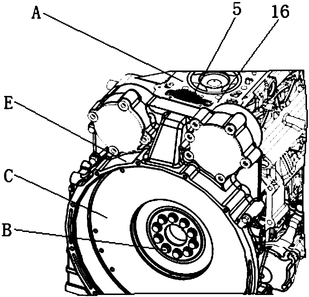
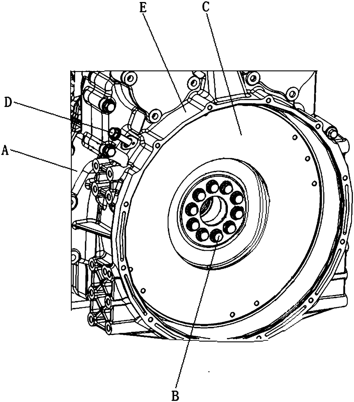
[0033] refer to Figure 1-12 , a tool for preventing the rotation of the flywheel of the rear power take-off engine, including a first bracket 1 and a second bracket 2 that can be folded or extended relatively, the first bracket 1 and the second bracket 2 can rotate relatively, and the first bracket 1 is provided with There is a first gear block 3 fixedly connected with it, and a second gear block 4 fixedly connected with it is provided on the second support 2, and the first support 1 includes a first step-off rod 7 connected sequentially from top to bottom, a first vertical Rod 8, first cross bar 9, correspondingly, second bracket 2 comprises the second give way bar 10, the second The vertical bar 11, the second cross bar 12, the upper end of the first give way bar 7 and the upper end of the second give way bar 10 are hinged to each other,...


PUM


Abstract

The invention discloses a tool for preventing a flywheel of a rear power take-off engine from rotation. The tool comprises a first support and a second support which can be oppositely folded and unfolded, wherein the first support is provided with a first gear block which is fixedly connected with the first support, the second support is provided with a second gear block which is fixedly connectedwith the second support, after folded, the first support and the second support can be used for simultaneously enabling the first gear block and the second gear block to be meshed with one gear in anengine gear system, and a spring connected with the first support and the second support is arranged between the first support and the second support. The tool can be used for effectively preventingthe flywheel and the gear system from rotation, thereby avoiding damaging a flywheel shell and a flywheel gear ring.

Description

technical field [0001] The invention relates to the technical field of engine assembly, more specifically, it relates to a tool for preventing the rotation of the flywheel of the rear power take-off engine. Background technique [0002] Such as figure 1 , 2 As shown, when the flywheel bolt B of engine A is taken off after disassembly and assembly, when there is torque acting on the flywheel bolt B, the flywheel C will rotate accordingly, which will result in the inability to apply the torque or remove the flywheel bolt. If the flywheel is assembled When bolt B is used, the torque cannot be applied or the torque is not enough, which will cause the torque to fail to meet the process requirements; at the same time, for the model with rear power take-off, the rotation of flywheel C will drive the timing gear to rotate. When the assembly has no positioning pin and the oil pump gear is For models with long waist holes, if the timing gear rotates, it will cause incorrect timing a...

Claims


Application Information

Patent Timeline
IPC IPC(8): B23P19/06
CPCB23P19/06
Inventor 冀智明刘建飞康玉霞黄韬何沛麇乔晓玲
Owner GUANGXI YUCHAI MASCH CO LTD
Why Eureka
Try Eureka