Eureka AIR delivers breakthrough ideas for toughest innovation challenges, trusted by R&D personnel around the world.

Cavitation jet cleaning cavitator

A cavitation and jet technology, applied in the field of cavitation, can solve the problems of limited cavitation effect and poor cleaning effect, and achieve the effects of enhancing the cavitation cleaning effect, reducing energy consumption, and enhancing the cavitation effect.

Pending Publication Date: 2018-08-21
ZHEJIANG SCI-TECH UNIV
View PDF15 Cites 7 Cited by
  • Summary
  • Abstract
  • Description
  • Claims
  • Application Information

AI Technical Summary

Problems solved by technology

Among them, when the shrinking device adopts a Venturi tube structure, due to the structural limitation of a single Venturi type, its cavitation effect is often very limited, and the cleaning effect is not good, so there are certain limitations in practical applications

Method used


Image

  • Cavitation jet cleaning cavitator
  • Cavitation jet cleaning cavitator
  • Cavitation jet cleaning cavitator

Examples


Embodiment 1

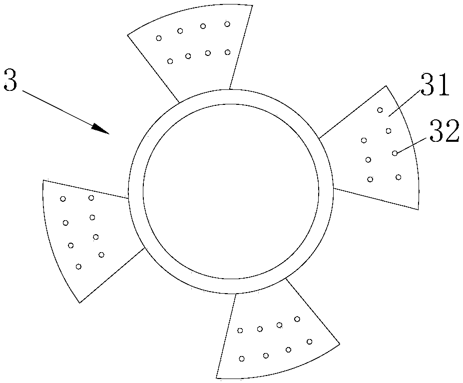
[0020] Embodiment one: if figure 1 , 2 As shown, this embodiment includes a pump and a casing 1, and a cavitation passage 2 is arranged in the casing 1, and the cavitation passage 2 includes an inlet 11 and an outlet 12, wherein the water outlet of the pump is connected to the inlet 11 of the cavitation passage 2 connected. The cavitation channel 2 includes two-stage Venturi lumens connected in series and connected in sequence. Each level of Venturi lumens includes an entrance section, a constriction section, and a throat section. Both the entrance section and the throat section are straight circular pipe structures, and The diameter of the throat section is 0.3 times the diameter of the inlet section. The two-level Venturi lumens are respectively the first-level Venturi lumen 21 and the second-level Venturi lumen 22. The first-level Venturi lumen 21 includes an entrance section 211, a constriction section 212, and a throat section 213. The second-level Venturi lumen Cavity...

Embodiment 2

[0024] Embodiment 2: The only difference from Embodiment 1 is that the through hole is a tapered hole, the opening on the tapered hole opposite to the entrance of the cavitation channel is a large opening, and the opening on the tapered hole opposite to the outlet of the cavitation channel is a small opening .

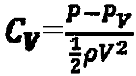
[0025] The cavitation number is a dimensionless parameter describing the cavitation state. The calculation formula of the cavitation number is as follows:

[0026]

[0027] The cavitation number at the midpoint of the Venturi tube axis can be calculated by this formula, in the formula: C V is the cavitation number, P is the incoming pressure of the liquid, P V is the saturated vapor pressure of the liquid at ambient temperature, ρ is the density of the liquid, and V is the flow rate of the liquid.

[0028] Among them, the smaller the cavitation number, the stronger the cavitation effect. Through the measurement and calculation of experimental data, the cavitation...


PUM


Abstract

The invention discloses a cavitation jet cleaning cavitator. The cavitation jet cleaning cavitator comprises a pump and a shell, wherein a cavitation channel is arranged in the shell, and the pump iscommunicated with the inlet of the cavitation channel; the cavitation channel comprises a plurality of Venturi tube cavities which are sequentially connected in series, wherein the inlet section of the first grade of Venturi tube cavity is communicated with the inlet of the cavitation channel, the throat section of the final stage of Venturi tube cavity is communicated with the outlet of the cavitation channel, and a diffusion section is also arranged between the throat section of the final stage of Venturi tube cavity and the outlet of the cavitation channel; and an axial flow turbine is mounted at the inlet section of the first grade of Venturi tube cavity, and blades of the axial flow turbine are provided with through holes penetrating through the blades. The cavitation effect is enhanced by utilizing multiple stages of Venturi tube cavities and the through holes in the blades, and the water flow is accelerated by the axial flow turbine so as to ensure that cavitation bubbles arriveat a cleaning region in time; cleaning is performed through the energy generated when the cavitation bubbles collapse, so that the cavitation efficiency is improved; and the pumping pressure requiredby cleaning can be effectively reduced, and the energy consumption can be reduced.

Description

technical field [0001] The invention relates to a cavitator, in particular to a cavitation jet cleaning cavitator. Background technique [0002] Cavitation cleaning technology is a green and environmentally friendly technology. After years of practice, it has been proved that this technology is a mature cleaning technology that has produced significant economic benefits in the national economy. Especially in recent years, cavitation cleaning technology has been expanded and extended in a wider range of fields, and has been deeply developed in various fields. There are many advantages of cavitation cleaning technology, for example: 1. The cleaned parts do not need to be cleaned; 2. It can clean parts with complex shapes and structures, especially in complex (narrow) spaces and harsh environments (harmful) 3. It is easy to realize mechanization and modernization to realize digital program control; 4. Water saving, energy saving, good cleaning effect, high efficiency, low cost...

Claims


Application Information

Patent Timeline
Patent Type & Authority Applications(China)
IPC IPC(8): B08B3/02B08B3/10
CPCB08B3/003B08B3/02B08B3/10
Inventor 林哲王博文朱祖超刘振兴
Owner ZHEJIANG SCI-TECH UNIV
Why Eureka
Eureka Blog
Learn More