
Municipal vehicle management treatment equipment

A technology for vehicle management and processing equipment, which is applied in the field of municipal vehicle management, and can solve the problems of manual spraying of paint on rollers, low work efficiency, and easy shaking

Inactive Publication Date: 2018-08-21
张茂排
View PDF0 Cites 0 Cited by
  • Summary
  • Abstract
  • Description
  • Claims
  • Application Information

AI Technical Summary

Problems solved by technology

[0004] In order to solve the above problems, the present invention provides a municipal vehicle management and processing equipment, which can solve the problems of low work efficiency when painting the spiral paint on the vehicle blocking piles, and the lack of positioning of the vehicle blocking piles according to the structure of the vehicle blocking piles. Fixing, vehicle resistance piles need to be manually scrubbed before painting, vehicle resistance piles are easy to shake when brushing, painting spiral paint requires manual spraying of paint on the rollers, and it is impossible to mechanize the car resistance piles. Problems such as poor painting effect of vehicle blocking piles; it can realize stable fixing of different types of vehicle blocking piles, scrub the surface of vehicle blocking piles, and automatically apply two-color spiral paint to the vehicle blocking piles, which has high work efficiency High, can limit and fix the vehicle resistance pile according to the structure of the vehicle resistance pile, automatically scrub the vehicle resistance pile before painting, the vehicle resistance pile will not shake when brushing, and automatically spray paint on the roller when the spiral paint is applied material, can be mechanized to brush the spiral paint on the car blocking pile, and the effect of mechanized painting on the car blocking pile is good, etc.

Method used


Image

  • Municipal vehicle management treatment equipment
  • Municipal vehicle management treatment equipment
  • Municipal vehicle management treatment equipment

Examples


Embodiment Construction

[0035] In order to make the technical means, creative features, objectives and effects achieved by the present invention easy to understand, the present invention will be further described below in conjunction with specific illustrations. It should be noted that, in the case of no conflict, the embodiments in the present application and the features in the embodiments can be combined with each other.

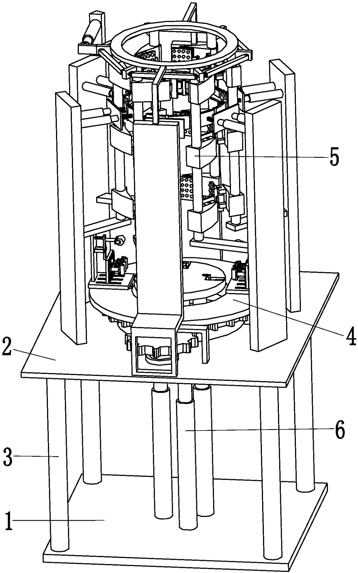
[0036] Such as Figure 1 to Figure 9 As shown, a municipal vehicle management and processing equipment includes a support plate 1, a top mounting plate 2, a support column 3, a brushing device 4, an extruding device 5 and a telescopic device 6, and the top mounting plate 2 passes through the support column 3 Installed on the top of the support plate 1, the middle part of the top mounting plate 2 is provided with a round hole, the top of the top mounting plate 2 is equipped with an extruding device 5, and the outside of the extruding device 5 is distributed with a brushing device...


PUM


Abstract

The invention relates to municipal vehicle management treatment equipment which comprises a support plate, a top mounting plate, support columns, coating devices, an extrusion device and telescopic devices, wherein the top mounting plate is mounted at the top of the support plate through the support columns; round holes are formed in the middle of the top mounting plate; the extrusion device is mounted at the top of the top mounting plate; the coating devices are distributed on the outer side of the extrusion device; the coating devices are mounted at the top of the top mounting plate; the telescopic devices are positioned inside the round holes of the top mounting plate; the telescopic devices are connected with the support plate. By adopting the equipment, the difficulties that a structure for limiting and fixing vehicle baffle piles is not available when a conventional vehicle baffle pile is coated by spiral paint, the vehicle baffle piles need to be scrubbed manually before being painted, the vehicle baffle piles are liable to waggle when being painted, the paint needs to be sprayed manually to rollers when the spiral paint is sprayed, the vehicle baffle piles cannot be mechanically coated by the spiral paint, and the vehicle baffle piles are poor in manual coating effect, can be solved.

Description

technical field [0001] The invention relates to the technical field of municipal vehicle management, in particular to a municipal vehicle management processing device. Background technique [0002] The material of the vehicle resistance pile is generally metal or stone. The upper end of the vehicle resistance pile is a cylindrical structure, and its lower end is a disc-shaped structure. Some of the discs at the lower end of the vehicle resistance pile are provided with mounting holes. The main purpose of installing the vehicle resistance pile vehicle It is for the purpose of not affecting the passage of pedestrians when the vehicle is parked. It belongs to the direction of municipal vehicle management. It is mainly used in landscape squares, residential quarters, large outdoor parking lots, sidewalks, parks and other places. [0003] The outer surface of the car resistance pile is generally painted with yellow and black spiral paint. First of all, the two colors have a stron...

Claims


Application Information

Patent Timeline
IPC IPC(8): B05C13/02B05C1/02B05C11/00B05C21/00
CPCB05C13/02B05C1/022B05C11/00B05C21/00
Inventor 张茂排
Owner 张茂排
Learn More