


Quick Research
Generate reliable direction feasibility study reports for your R&D in just a few steps.

Technical Q&A
Discover and master advanced knowledge NOW. Basics, ideas, possibilities, all at once.

Find Solutions
As an expert in R&D theories, this can generate solutions to your technical problems instantly.

Evaluate Feasibility
Analyze your overall solution with one click, know your potential R&D risks in advance.

Monitor Landscape
Get weekly tech updates, stay abreast of the latest tech innovations and key insights.
INFORMATION PROCESSING APPARATUS AND method
A technology of information processing equipment and display area, which is applied in image data processing, electrical digital data processing, and location-based services, etc., can solve problems such as grasping the position of objects, and achieve the effect of avoiding excessive reduction.
- Summary
- Abstract
- Description
- Claims
- Application Information
AI Technical Summary
Problems solved by technology
Method used
Image

Examples
Embodiment approach
[0099] System configuration example
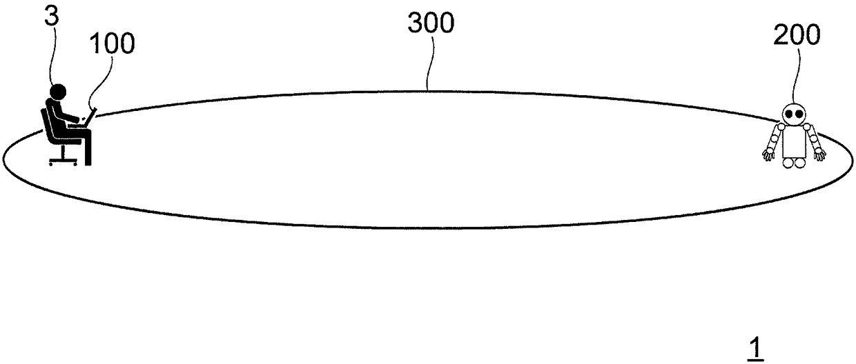
[0100] figure 1 A conceptual configuration of an information processing system 1 as an example of the exemplary embodiment is shown. The information processing system 1 includes an information terminal 100 operated by a user 3 and a robot 200 under the management of the user 3 . Information terminal 100 is an example of an information processing device. Robot 200 is an example of a movable object.
[0101] although figure 1 A notebook computer is shown as an example of the information terminal 100, and the information terminal 100 may be any type of device as long as the device has a function of displaying positional information on the robot 200 in cooperation with a display device mounted on the information terminal 100 or an external display device. Can. For example, the information terminal 100 may be (1) an image display device such as a desktop computer, a tablet computer, a smart watch, a smart phone, a digital camera, a video c...
example 1
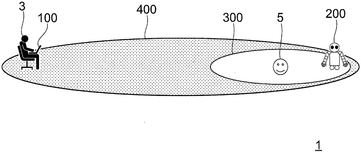
[0192] Figure 36A and Figure 36B Showing a display example when the user 3 and the robot 200 approach each other, Figure 36A shows the positions of the user 3 and the robot 200 in the management area 300, Figure 36B A display example of the positional relationship in the virtual management area 300A is shown. because Figure 36A and Figure 36B A display example when the robot 200 approaches the user 3 is shown, so an image 200A associated with the robot 200 having a relatively large display size is displayed near the image 3B indicating the user 3 . refer to Figure 36A and Figure 36B , it is found that the robot 200 is located near the center of the management area 300 .
[0193] Figure 37A and Figure 37B Showing a display example when the user 3 and the robot 200 are far away from each other, Figure 37A shows the positions of the user 3 and the robot 200 in the management area 300, Figure 37B A display example of the positional relationship in the virtual ...
example 2
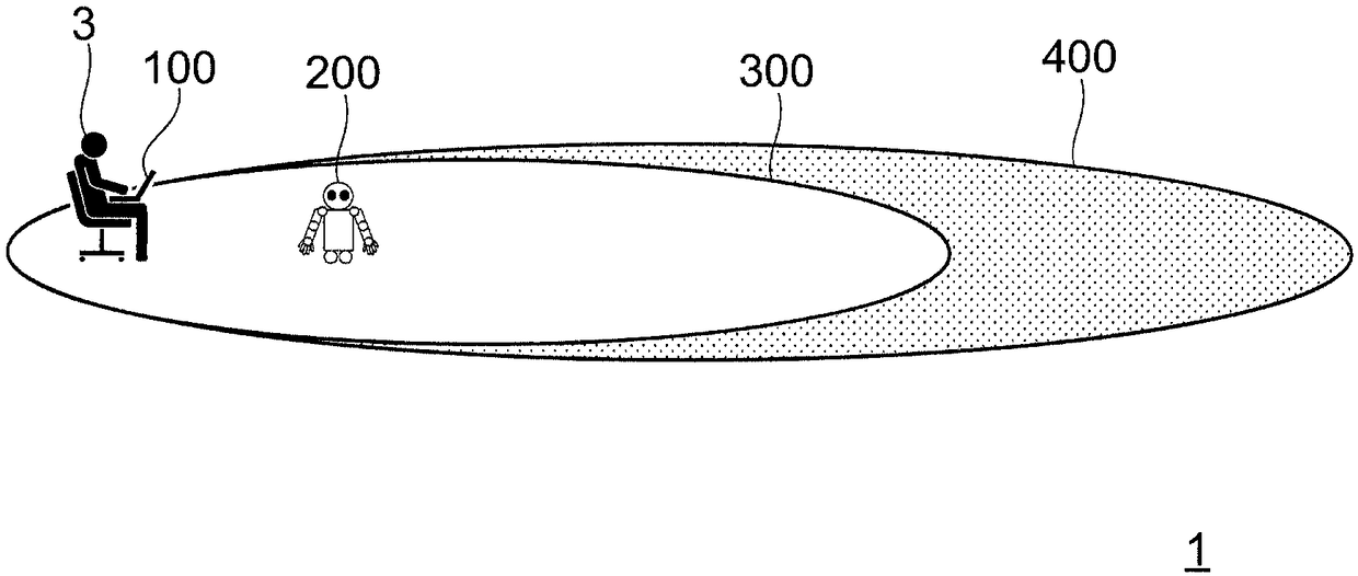
[0196] Figure 38A and Figure 38B Showing a display example when the user 3 is located near the center of the management area 300, Figure 38A shows the positions of the user 3 and the robot 200 in the management area 300, Figure 38B A display example of the positional relationship in the virtual management area 300A is shown. Although because the robot 200 is located at the corner of the management area 300 Figure 38A and Figure 38B show with Figure 37A and Figure 37B The example in is similar to the example in , but the distance between the user 3 and the robot 200 is small, so the displayed size of the image 200A associated with the robot 200 is not significantly reduced.
PUM
 Abstract
Description
Claims
Application Information
 - R&D Engineer
- R&D Manager
- IP Professional
- Industry Leading Data Capabilities
- Powerful AI technology
- Patent DNA Extraction
Browse by: Latest US Patents, China's latest patents, Technical Efficacy Thesaurus, Application Domain, Technology Topic, Popular Technical Reports.
© 2024 PatSnap. All rights reserved.Legal|Privacy policy|Modern Slavery Act Transparency Statement|Sitemap|About US| Contact US: help@patsnap.com