An electronic current transformer based on Rogowski coil and its characteristic analysis method

A technology of current transformer and Rogowski coil is applied in the field of electronic current transformer and its characteristic analysis, which can solve the problems of low reliability of the transformer, malfunction of relay protection, and inability to synchronize the collected data.

Active Publication Date: 2021-01-29
STATE GRID ANHUI ELECTRIC POWER CO LTD +1
View PDF5 Cites 0 Cited by
  • Summary
  • Abstract
  • Description
  • Claims
  • Application Information

AI Technical Summary

Problems solved by technology

[0004] Aiming at the deficiencies described in the above-mentioned prior art, the present invention provides an electronic current transformer based on Rogowski coils and its characteristic analysis method, which is for the overall design, development and analysis of the steady-state characteristics and transient state of the electronic current transformer. The characteristics are researched to provide analysis platform and experimental data. The obtained experimental data is used for the research and development of the key technology of the overall anti-vibration performance of electronic current transformers, and solves the problem of its low reliability compared with traditional transformers and the difference with traditional electromagnetic current transformers. When transformers are mixed in relay protection, the collected data cannot be synchronized, and the transmission and transformation characteristics are different, which will cause compatibility problems such as relay protection misoperation

Method used


Image

  • An electronic current transformer based on Rogowski coil and its characteristic analysis method
  • An electronic current transformer based on Rogowski coil and its characteristic analysis method
  • An electronic current transformer based on Rogowski coil and its characteristic analysis method

Examples


Embodiment 1

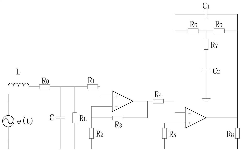
[0069]Example 1: Such asfigure 1 As shown, an electronic current transformer based on a Rogowski coil includes a Rogowski coil equivalent circuit, an amplifier circuit, and an integrating circuit; the integrating circuit is connected to the Rogowski coil equivalent circuit through the amplifier circuit; the Rogowski coil equivalent circuit includes Induced electromotive force e(t), equivalent resistance R0, Coil inductance L, coil equivalent stray capacitance C and sampling resistance RL; Equivalent resistance R0, The coil inductance L and the coil equivalent stray capacitance C are connected in series on the induced electromotive force e(t), the sampling resistance RLConnect the equivalent stray capacitance C of the coil in parallel to obtain the sampling voltage u1(t); The amplifying circuit includes a first operational amplifier, a resistor R1, a resistor R2, and a resistor R3; the same direction input terminal of the first operational amplifier is connected to an output terminal...

Embodiment 2

[0071]Embodiment 2: A method for analyzing the characteristics of an electronic current transformer based on a Rogowski coil, the steps are as follows: S1, the equivalent circuit of the Rogowski coil is constructed;

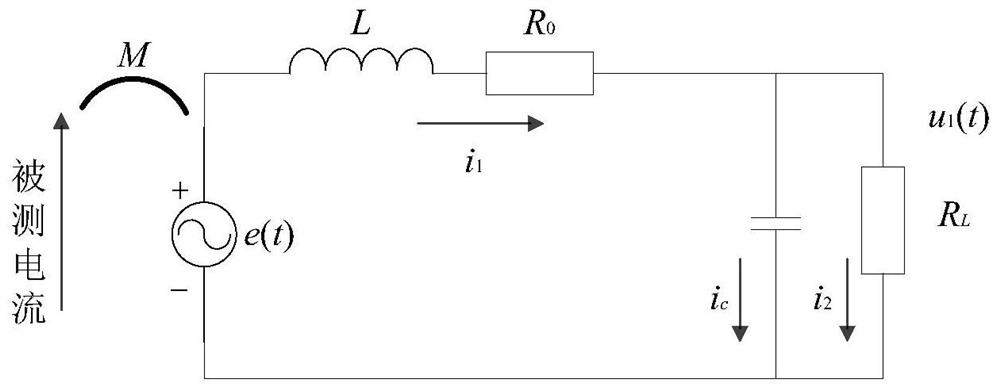
[0072]The Rogowski coil equivalent circuit, such asfigure 2Shown, including induced electromotive force e(t), equivalent resistance R0, Coil inductance L, coil equivalent stray capacitance C and sampling resistance RL; Equivalent resistance R0, The coil inductance L and the coil equivalent stray capacitance C are connected in series on the induced electromotive force e(t), the sampling resistance RLConnect the equivalent stray capacitance C of the coil in parallel to obtain the sampling voltage u1(t).

[0073]S2, obtain the transfer function of the Rogowski coil equivalent circuit;

[0074]S2.1, according to step S1, obtain the voltage and current equation of the Rogowski coil equivalent circuit:

[0075]

[0076]

[0077]

[0078]S2.2, combining the three equations in step S2.1, we can ge...


PUM


Abstract

The invention discloses an electronic current transformer based on a Rogowski coil, which comprises a Rogowski coil equivalent circuit, an amplifying circuit and an integrating circuit; the integrating circuit is connected with the Rogowski coil equivalent circuit through the amplifying circuit. In the established Rogowski coil electronic current transformer model, the Rogowski coil equivalent circuit is used for the parameters of the equivalent coil, and the voltage signal is output through the sampling resistor; the amplifying circuit amplifies the small voltage signal output by the coil for use by the following integral components ;The last integral circuit is the most important part. Firstly, a good integral link can amplify the signal to be restored on the one hand, ensure the accuracy of measurement and reduce the error. On the other hand, it can optimize the signal and filter out useless interference. And according to the established Rogowski coil electronic current transformer model, the simulation analysis is carried out to analyze its characteristics, and to provide technical support for the practical process of electronic current transformer.

Description

Technical field[0001]The technical field of the current transformer of the present invention specifically relates to an electronic current transformer based on a Rogowski coil and a characteristic analysis method thereof.Background technique[0002]With the formation of the grid pattern of "West-to-East Power Transmission, North-South Interconnection, and National Networking", my country's power system is developing rapidly in the direction of large capacity and high voltage. Current transformers are used as power measurement equipment for the power system to monitor the operating status of primary equipment. , It is an important component in the relay protection system to provide real and reliable electrical quantities for the secondary equipment. With the continuous improvement of grid voltage levels and the increasing expansion of power system capacity, traditional electromagnetic current transformers have exposed disadvantages such as difficulty in insulation and insufficient line...

Claims


Application Information

Patent Timeline
Patent Type & Authority Patents(China)
IPC IPC(8): G01R15/18G01R35/02
CPCG01R15/181G01R35/02
Inventor 叶远波吴迪陈实谢民王同文孙月琴程小平王薇郑浩汪胜和汪玉高博郑国强郝治国徐靖东张瀚文
Owner STATE GRID ANHUI ELECTRIC POWER CO LTD
Why Eureka
Try Eureka