
A fixture for positioning and pasting strain gauges on round rod members

A technology of strain gauges and components, applied in the direction of connecting components, material gluing, mechanical equipment, etc., can solve the problems of inability to guarantee the symmetry of the patch position, low data measurement accuracy, and poor operation consistency, so as to facilitate installation and disassembly and avoid impact Accuracy, the effect of ensuring consistency

Active Publication Date: 2020-11-03
CHONGQING CHANGAN AUTOMOBILE CO LTD
View PDF7 Cites 0 Cited by
  • Summary
  • Abstract
  • Description
  • Claims
  • Application Information

AI Technical Summary

Problems solved by technology

[0004] (1) Steel rulers and paper strips cannot guarantee the symmetry of the patch position, resulting in low data measurement accuracy;
[0005] (2) The patch positions drawn by each person using steel rulers and paper strips are very different, and the operation consistency is poor;
[0006] (3) The paper strip positioning method needs to cut paper strips for two-force round rods of different diameters (referring to cylindrical straight rods that are only stressed at both ends and are in a balanced state) each time, and the work efficiency is low.

Method used


Image

  • A fixture for positioning and pasting strain gauges on round rod members
  • A fixture for positioning and pasting strain gauges on round rod members
  • A fixture for positioning and pasting strain gauges on round rod members

Examples


Embodiment Construction

[0030] The present invention will be further described below in conjunction with the accompanying drawings.

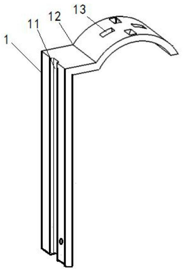
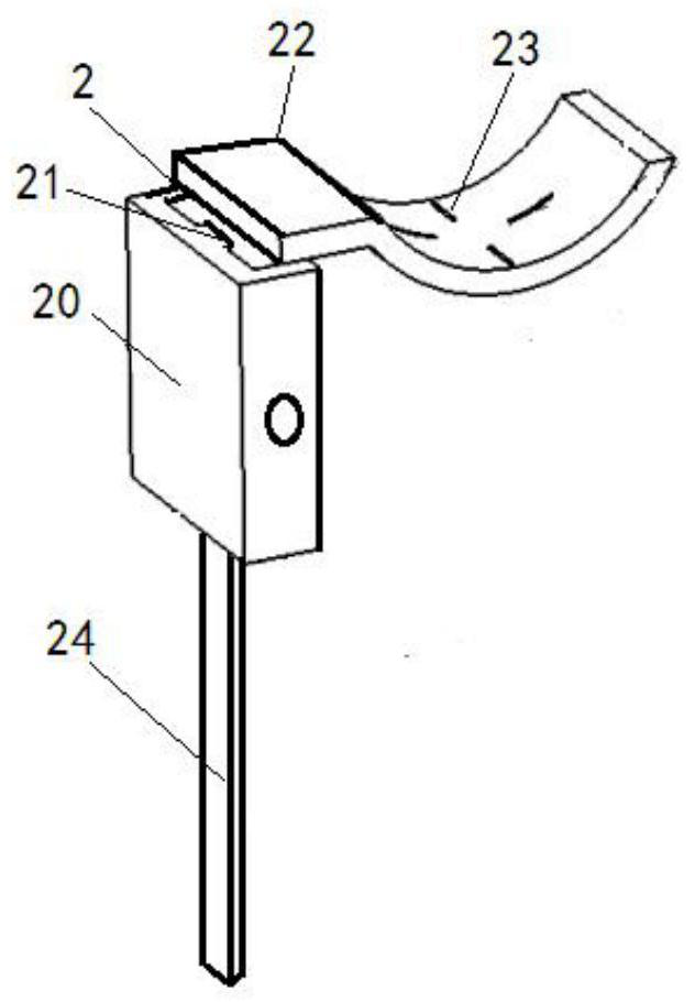
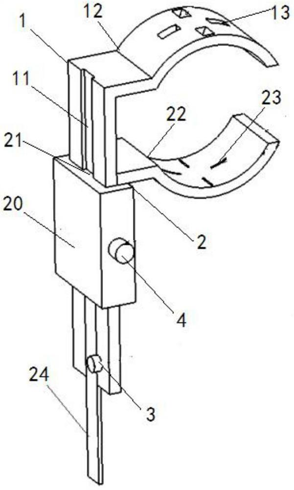
[0031] see figure 1 , figure 2 ,and image 3 The shown clamp for positioning and pasting strain gauges on a round bar member includes an upper clamping ruler 1 and a lower clamping ruler 2 matched therewith, and its features are:

[0032] The upper clamping ruler 1 is composed of a ruler part and an upper clamp 12 connected to the upper end of the ruler part; a through chute 11 is provided on the ruler part of the upper clamping ruler 1; the upper clamp 12 is composed of The straight part and the arc part connected to the right end are formed in a "sickle shape", and the straight part is vertically connected to the right side of the upper end of the ruler part, and the arc opening of the arc part is downward;

[0033] The lower clamping ruler 2 is composed of a sliding sleeve 20, a lower chuck 22 connected to the right part of the upper end of the sliding sleeve 20...


PUM


Abstract

The invention relates to a clamp for positioning and pasting a strain gauge on a round rod component. The clamp comprises an upper clamping ruler and a lower clamping ruler matched with the upper clamping ruler, the upper clamping ruler is composed of a ruler body part and an upper clamping head connected to the upper end of the ruler body part, a through sliding groove is formed in the ruler bodypart of the upper clamping ruler, the lower clamping ruler is composed of a sliding sleeve, a lower clamping head connected to the right part of the upper end of the sliding sleeve, and a guide rod connected to the lower end of the sliding sleeve, a through rectangular hole is formed in the center of the sliding sleeve, a sliding rail penetrating through the sliding sleeve is arranged in the middle of the left side of the rectangular hole, the upper clamping ruler is in sliding fit with the rectangular hole in the center of the sliding sleeve, and the sliding rail of the sliding sleeve is insliding fit with the sliding groove of the ruler body part of the upper clamping ruler. According to the clamp for positioning and pasting the strain gauge on the round rod component, the pasting position of the strain gauge can be ensured to be precise, the requirement for high pasting symmetry of the strain gauge is met, the mounting and dismounting are simple and convenient, and the working efficiency can be remarkably improved; and the advantages of being simple and convenient to mount and dismounted, good in scribing position symmetry and suitable for the round rod components of multipledimensions and shaft diameters are achieved.

Description

technical field [0001] The invention relates to performance testing of automobile components, in particular to a fixture for positioning and pasting strain gauges on round rod components. Background technique [0002] The collection of road load spectrum (referred to as road spectrum) is an extremely important task in the process of automobile research and development. It is one of the important means to study the reliability of the vehicle, and provides a scientific basis for the fatigue life design of the vehicle and parts. [0003] At present, major domestic automobile companies have carried out road spectrum collection work one after another. When preparing for road spectrum collection, it is necessary to symmetrically paste strain gauges on specific positions of parts and components to transform parts into specific sensors. This work has high requirements on the symmetry of strain gauge pasting. At present, there is no special tooling and method for marking the placeme...

Claims


Application Information

Patent Timeline
Patent Type & Authority Patents(China)
IPC IPC(8): F16B11/00
CPCF16B11/006
Inventor 罗英张小琳方川
Owner CHONGQING CHANGAN AUTOMOBILE CO LTD
Learn More