Titanium material heat exchange device

A technology of heat exchange device and titanium material, which is applied in the direction of heat exchanger type, heat exchanger shell, indirect heat exchanger, etc., which can solve the problem of the overall structural stability and low strength of the heat exchange device, which affects the safety of the heat exchange device , short service life of heat exchange tubes, etc., to reduce labor intensity of workers, improve structural stability and strength, and prolong service life

Pending Publication Date: 2018-08-17
江苏龙净节能科技有限公司
View PDF7 Cites 0 Cited by
  • Summary
  • Abstract
  • Description
  • Claims
  • Application Information

AI Technical Summary

Problems solved by technology

The above-mentioned heat exchange device has the following disadvantages: (1) The carbon steel heat exchange tube is installed directly in contact with the carbon steel side plate, and the carbon steel heat exchange tube is easily damaged by friction with the carbon steel side plate during use, resulting in heat exchange The service life of the tube is short; (2) The overall structural stability and strength of the heat exchange device is low; (3) Due to the large number of carbon steel elbows, welding carbon steel elbows is not only time-consuming, labor-intensive, but also prone to weld joints Welding defects affect the safety of the heat exchange device; (4) Poor corrosion resistance, short service life and high cost

Method used


Image

  • Titanium material heat exchange device
  • Titanium material heat exchange device
  • Titanium material heat exchange device

Examples


Embodiment Construction

[0016] The present invention will be further described below in conjunction with the drawings and specific embodiments.

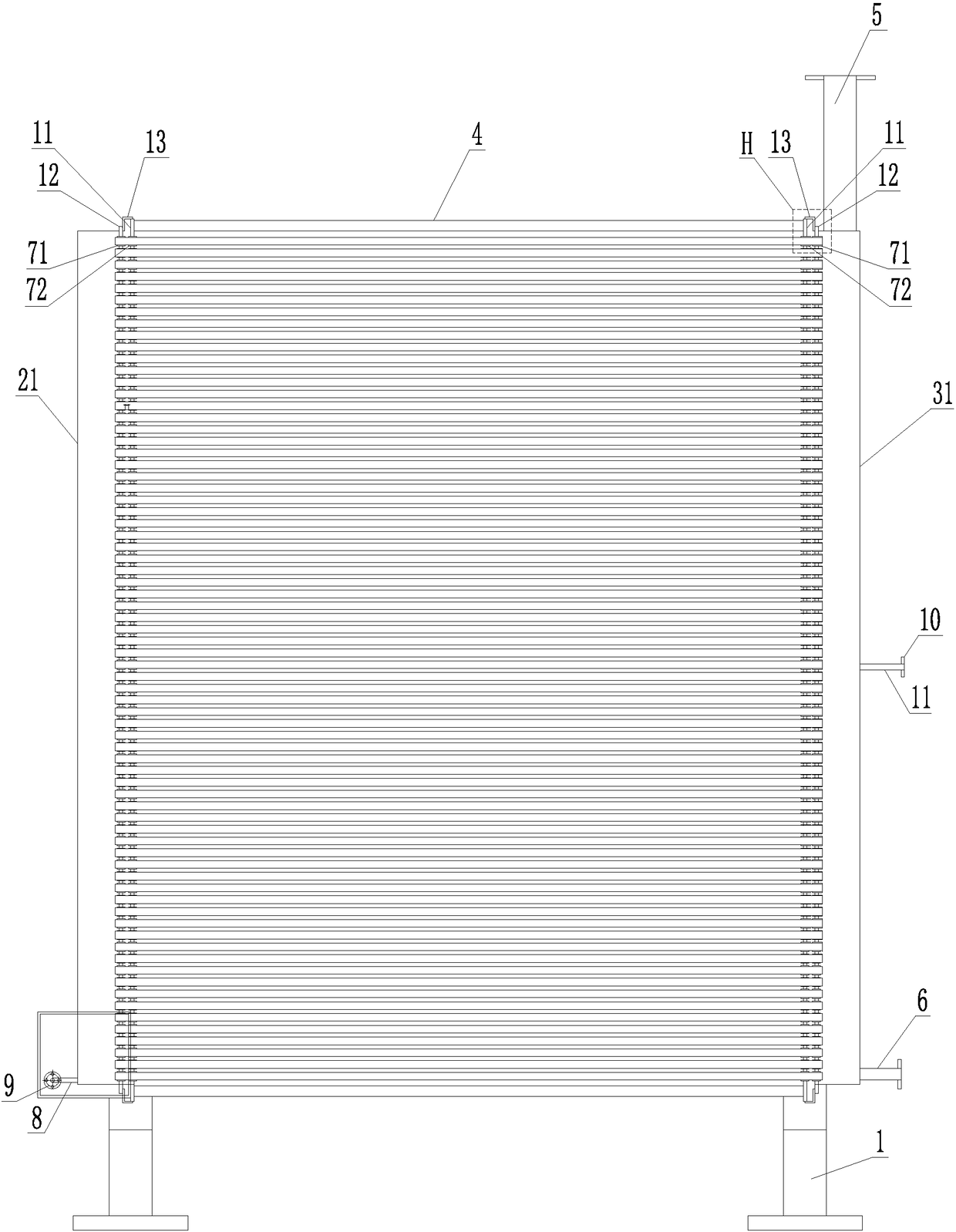
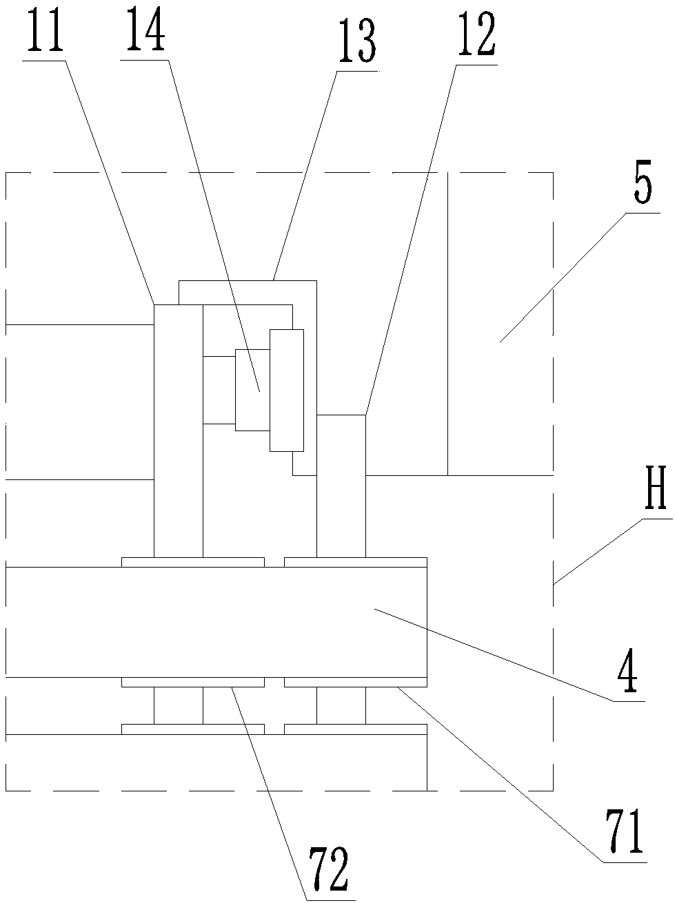
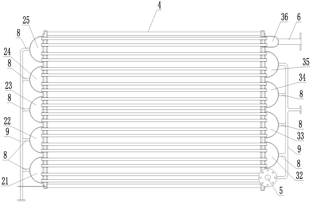
[0017] Such as figure 1 , figure 2 , image 3 As shown, the described titanium heat exchange device includes a frame 1, and titanium side plates are respectively provided on the left and right sides of the top of the frame 1, and a plurality of opposite sides are respectively provided on the outer sides of the two titanium side plates. Independent titanium material header, all titanium material headers are connected in series through several titanium material heat exchange tubes supported between two titanium material side plates, so that all titanium material headers and all titanium material heat exchange tubes A number of parallel serpentine heat exchange pipelines are formed together. In this embodiment, the left first titanium material header 21 and the left second titanium material header are sequentially arranged from front to back on the outside of th...


PUM


Abstract

The invention discloses a titanium material heat exchange device. The device comprises two titanium material side plates which are distributed left and right, and a plurality of relatively independenttitanium material collecting boxes are arranged on the outer sides of the two titanium material side plates correspondingly; all the titanium material collecting boxes are connected in series througha plurality of titanium material heat exchange tubes supported between the two titanium material side plates, so that all the titanium material collecting boxes and all the titanium material heat exchange tubes form a plurality of parallel S-shaped heat exchange pipelines; a steam inlet pipe is arranged at the top of the titanium material collecting box located at the head position of the S-shaped heat exchange pipelines, and a steam outlet pipe is arranged at the bottom of the titanium material collecting box at the tail position of the S-shaped heat exchange pipelines; and a protective sleeve is arranged on the portion, in contact with each titanium material side plate, of each titanium material heat exchange tube in a sleeving mode. The titanium material heat exchange device has the advantages that the structure is compact, the situation that the titanium material heat exchange tubes are damaged due to friction between the titanium material heat exchange tubes and the titanium material side plate in the using process can be avoided, and the service life of the heat exchange tubes is long; and the overall structure is high in stability and strength, the assembling efficiency ishigh, and the use safety is high.

Description

Technical field [0001] The invention relates to the technical field of flue gas heat exchange equipment, in particular to a titanium heat exchange device. Background technique [0002] The exhaust gas produced by the PTA production equipment during the production process will be discharged into the outside through the flue and chimney. Because the exhaust gas produced by the PTA production equipment during the production process is low-temperature saturated flue gas, in order to avoid low-temperature saturated flue gas from being discharged into the outside through the chimney In the process, white flocs are formed and the chimney is damaged. Generally, it is necessary to install a heat exchange device to heat the low-temperature saturated flue gas in the flue. The structure of the heat exchange device currently in use is as follows: It includes two single-layer carbon steel side plates distributed left and right. Between the two carbon steel side plates, several layers of carbon...

Claims


Application Information

Patent Timeline
Patent Type & Authority Applications(China)
IPC IPC(8): F28D7/08F28F9/02F28F21/08
CPCF28D7/085F28F9/02F28F21/086
Inventor 魏树林罗如生罗跃彬吴长森顾建清彭文熙杨文贞
Owner 江苏龙净节能科技有限公司
Why Eureka
Try Eureka