
Reinforcing steel bar carrying robot structure

A technology for handling robots and steel bars, applied in the field of handling robots, can solve the problems of large size and structure of gantry hangers, potential safety hazards, and difficulty in turning steel bars, so as to facilitate the transportation of steel bars, avoid personnel injuries, and save time.

Inactive Publication Date: 2018-08-17
SUZHOU LAIJIN ELECTROMECHANICAL AUTOMATION CO LTD
View PDF0 Cites 2 Cited by
  • Summary
  • Abstract
  • Description
  • Claims
  • Application Information

AI Technical Summary

Problems solved by technology

[0002] After the steel bar is produced, it needs to be transported to the warehouse for storage. The existing transportation method is through the gantry hanger, which is suspended by the gantry hanger and then transported to the warehouse for storage. The gantry hanger has a large volume structure and requires a large space to operate, and It is necessary to maintain the balance of the steel bars during the suspension process, which is cumbersome to operate and has potential safety hazards. During the handling process, it is difficult to turn the steel bars because of the different placement positions. Therefore, further improvement is needed

Method used


Image

  • Reinforcing steel bar carrying robot structure
  • Reinforcing steel bar carrying robot structure

Examples


Embodiment Construction

[0016] The preferred embodiments of the present invention will be described below in conjunction with the accompanying drawings. It should be understood that the preferred embodiments described here are only used to illustrate and explain the present invention, and are not intended to limit the present invention.

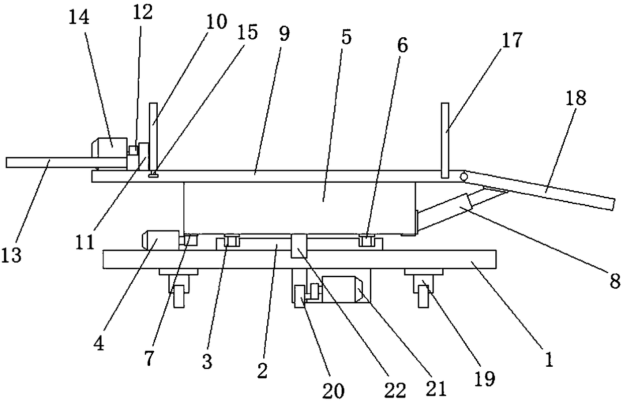
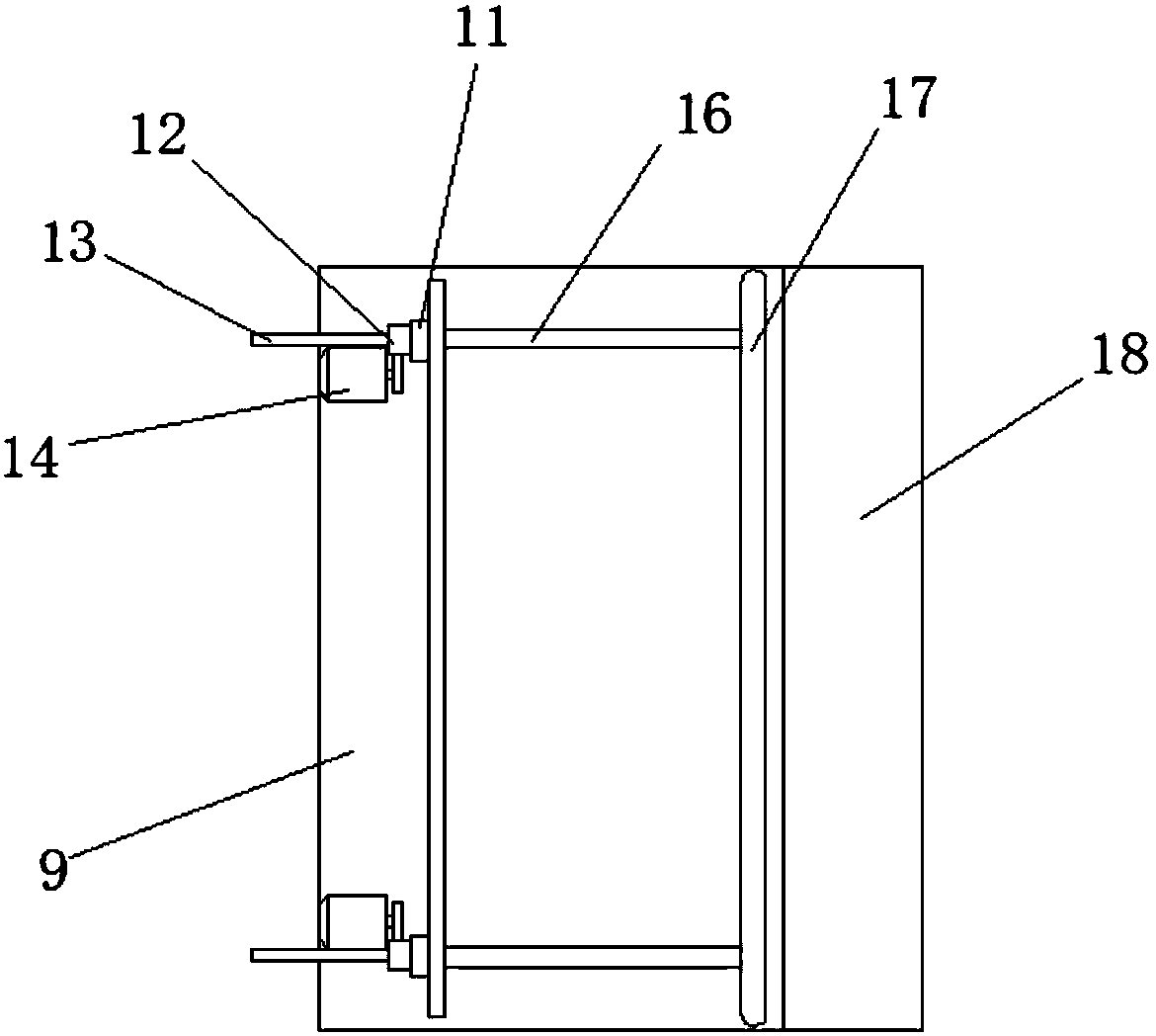
[0017] Such as Figure 1-Figure 2 As shown, a steel bar handling robot structure includes a base 1, a rotating disk 2 is provided on the top of the base 1, a rotating groove 3 is provided on the top of the rotating disk 2, and a rotating motor is provided on one side of the rotating disk 2. 4. There is a supporting seat 5 above the rotating disk 2, and a rotating wheel 6 is provided at the bottom of the supporting seat 5, which can make the placing plate 9 rotate, and change the direction of the sliding plate 18 according to the placing position, thereby changing the direction of unloading steel bars , and the rotating wheel 6 is located in the inner cavity of the r...


PUM


Abstract

The invention relates to a reinforcing steel bar carrying robot structure which comprises a base. A rotary disc is arranged at the top of the base. A rotary groove is formed in the top of the rotary disc. A rotary motor is arranged on one side of the rotary disc. A supporting seat is arranged above the rotary disc. Rotary wheels are arranged at the bottom of the supporting seat and arranged in rotary groove inner cavities. A rack is arranged on the edge at the bottom of the supporting seat. The rotary motor is connected with the rack through a gear. A telescopic rod is arranged on one side ofthe supporting seat. A containing board is arranged at the top of the supporting seat. A push board is arranged on one side at the top of the containing board. Bearing seats are symmetrically arrangedon one side of the push board and fixedly connected with the containing board. A nut is connected with one side of each bearing seat through a bearing. Lead screws are sleeved with inner cavities ofthe nuts. The reinforcing steel bar carrying robot structure is simple and reasonable in design, reinforcing steel bars can be conveniently transported, reinforcing steel bar transportation is not limited to rectilinear track transportation, and meanwhile the placing direction of the reinforcing steel bars can be changed according to a placing site.

Description

technical field [0001] The invention relates to a steel bar handling robot structure, which belongs to the technical field of handling robots. Background technique [0002] After the steel bar is produced, it needs to be transported to the warehouse for storage. The existing transportation method is through the gantry hanger, which is suspended by the gantry hanger and then transported to the warehouse for storage. The gantry hanger has a large volume structure and requires a large space to operate, and It is necessary to maintain the balance of the steel bars during the suspension process, which is cumbersome to operate and has potential safety hazards. During the handling process, it is difficult to turn the steel bars because of the different placement positions. Therefore, further improvement is needed. Contents of the invention [0003] The technical problem to be solved in the present invention overcomes the existing defects, and provides a steel bar handling robot s...

Claims


Application Information

Patent Timeline
Patent Type & Authority Applications(China)
IPC IPC(8): B60P3/00B60P1/43
CPCB60P3/00
Inventor 费吕平顾丽娟
Owner SUZHOU LAIJIN ELECTROMECHANICAL AUTOMATION CO LTD
Learn More