
Adjustable clamping device for workpiece fastening

A clamping device and adjustable technology, applied in the direction of feeding device, positioning device, storage device, etc., can solve the problems of reducing production efficiency, increasing time consumption, occupying large capital and equipment resources, etc.

Inactive Publication Date: 2018-08-17
重庆恩光科技有限公司
View PDF6 Cites 0 Cited by
  • Summary
  • Abstract
  • Description
  • Claims
  • Application Information

AI Technical Summary

Problems solved by technology

[0002] In the process of assembling plate workpieces in the field of machining, it often occurs that the fastening of some workpieces requires fine fastening technology. If a special mold is developed for this kind of workpiece, it will require a large amount of tooling costs, and the mold is heavy. At the same time The workpiece usually needs to be stamped by stamping equipment during assembly, but the use of stamping equipment not only increases time consumption and reduces production efficiency, but also takes up relatively large capital and equipment resources, increasing the cost

Method used


Image

  • Adjustable clamping device for workpiece fastening
  • Adjustable clamping device for workpiece fastening
  • Adjustable clamping device for workpiece fastening

Examples


Embodiment Construction

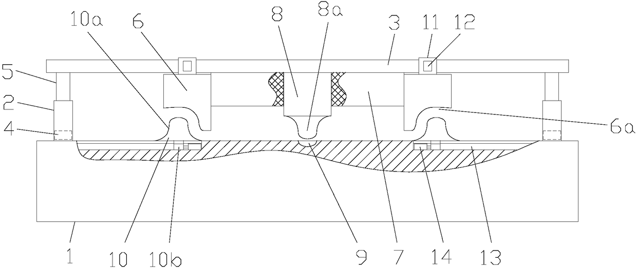
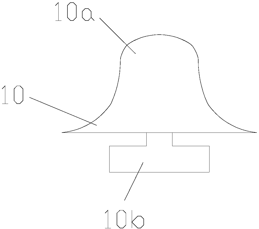
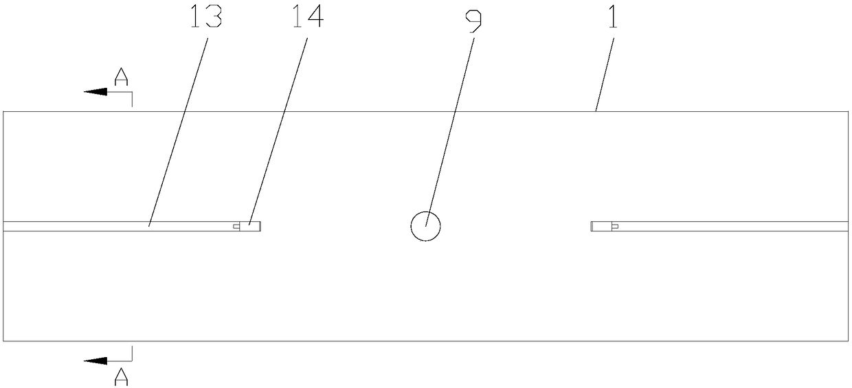
[0018] figure 1 is a schematic diagram of the structure of the present invention, figure 2 It is a structural schematic diagram of the top block of the present invention, image 3 It is a schematic diagram of the structure of the working platform of the present invention, Figure 4 for image 3 The schematic diagram of the A-A direction, as shown in the figure: the adjustable clamping device for workpiece fastening in this embodiment includes a working platform 1 and a pressing mechanism for pressing and fastening the workpiece, and the pressing mechanism includes a support frame, a Compression block I6, compression block II8, buffer member 7, the support frame includes lifting rod assemblies symmetrically arranged on the lateral sides of the working platform 1 and a transverse support beam 3 fixed on the top of the two lifting rod assemblies, the compression block II8 and The buffer member 7 is fixed on the bottom of the middle of the transverse support beam 3, and the nu...


PUM


Abstract

The invention discloses an adjustable clamping device for workpiece fastening. The adjustable clamping device for workpiece fastening comprise a working platform and a pressing mechanism, wherein a support frame of the pressing mechanism comprises a lifting rod assembly and a cross support beam; a pressing block II and a buffer piece are fixed to the bottom part of the middle of the cross supportbeam; two pressing blocks I are slidably arranged on the cross support beam along a horizontal direction; two sliding mechanisms are arranged on the cross support beam; two ejecting blocks are arranged on the top surface of the working platform, are located right under the corresponding pressing blocks I, and are slidably arranged on the working platform along a horizontal direction; arc-shaped notch parts are arranged at the lower ends of the two pressing blocks I; ball heads I are arranged at the upper ends of the two ejecting blocks; a ball head II is arranged at the lower end of the pressing block II; and a concave cavity is arranged on the top surface of the working platform. The adjustable clamping device for workpiece fastening provided by the invention can be used for high-efficiently and quickly fastening workpieces, is beneficial to improving the production efficiency and reducing the cost, can realize stamping operation, and is simple in overall structure, convenient to assemble and disassemble, capable of being freely adjusted according to the sizes of the workpieces, wide in application range and convenient to use.

Description

technical field [0001] The invention relates to the field of mechanical processing equipment, in particular to an adjustable clamping device for workpiece fastening. Background technique [0002] In the process of assembling plate workpieces in the machining field, it often occurs that the fastening of some workpieces requires a fine fastening process. If a special mold is developed for such workpieces, a large amount of tooling costs are required, and the mold is heavy and at the same time. The workpiece usually needs to be punched by punching equipment during assembly, and the use of punching equipment not only increases time-consuming and reduces production efficiency, but also occupies relatively large capital and equipment resources, increasing costs. [0003] Therefore, there is an urgent need to develop a method that can not only realize efficient and fast fastening of workpieces, improve production efficiency, reduce costs, but also realize punching operations, and h...

Claims


Application Information

Patent Timeline
Patent Type & Authority Applications(China)
IPC IPC(8): B21D39/00B21D43/00
CPCB21D39/00B21D43/003
Inventor 王守中
Owner 重庆恩光科技有限公司
Learn More