
Method and device for calibrating radio frequency transmitting power

A technology of radio frequency transmission power and calibration method, applied in the field of radio frequency transmission power calibration method and equipment, can solve the problems of inability to guarantee low-power transmission accuracy, insufficient product device accuracy, large transmission power deviation, etc., so as to improve efficiency and improve Radio frequency transmission accuracy, the effect of improving the transmission accuracy

Inactive Publication Date: 2018-08-14
SICHUAN FEIXUN INFORMATION TECH CO LTD
View PDF4 Cites 12 Cited by
  • Summary
  • Abstract
  • Description
  • Claims
  • Application Information

AI Technical Summary

Problems solved by technology

[0009] The TSSI voltage vs PA theoretical power value is not linear in the entire power range. In the small power range, such as 0~10dBm, the variation range of the TSSI voltage is relatively small. It is necessary to output a power range of 10dB in a small range of TSSI voltage. Due to the Due to device limitations, the accuracy of the product device is not enough, resulting in a large deviation in the corresponding transmission power, and the transmission accuracy at low power cannot be guaranteed

Method used


Image

  • Method and device for calibrating radio frequency transmitting power
  • Method and device for calibrating radio frequency transmitting power
  • Method and device for calibrating radio frequency transmitting power

Examples


Embodiment Construction

[0047] In order to more clearly illustrate the embodiments of the present invention or the technical solutions in the prior art, the specific implementation manners of the present invention will be described below with reference to the accompanying drawings. Obviously, the accompanying drawings in the following description are only some embodiments of the present invention, and those skilled in the art can obtain other accompanying drawings based on these drawings and obtain other implementations.

[0048] In order to make the drawing concise, each drawing only schematically shows the parts related to the present invention, and they do not represent the actual structure of the product. In addition, to make the drawings concise and easy to understand, in some drawings, only one of the components having the same structure or function is schematically shown, or only one of them is marked. Herein, "a" not only means "only one", but also means "more than one".

[0049] In one emb...


PUM


Abstract

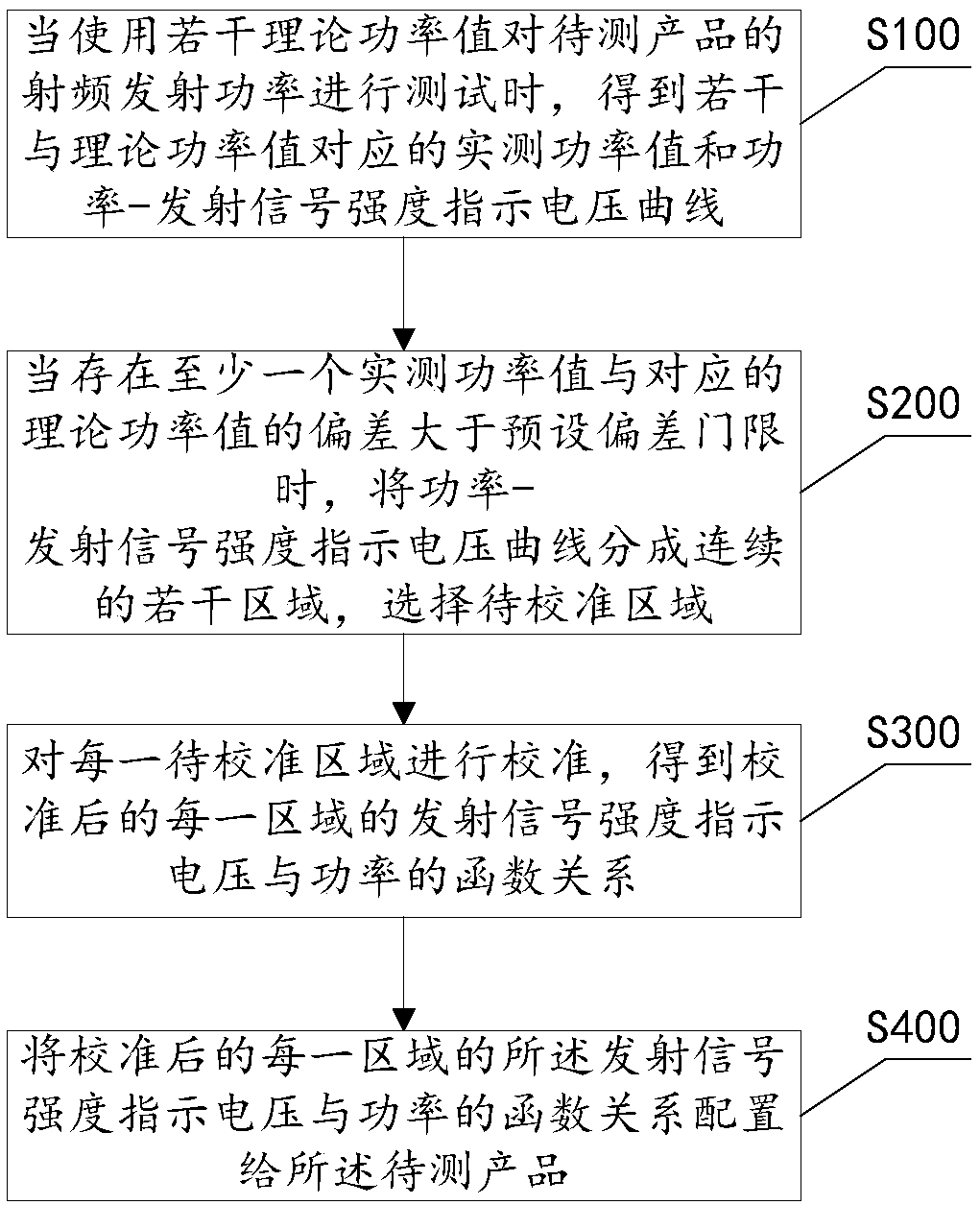
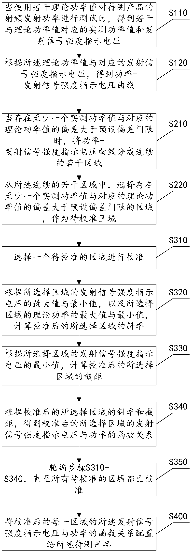
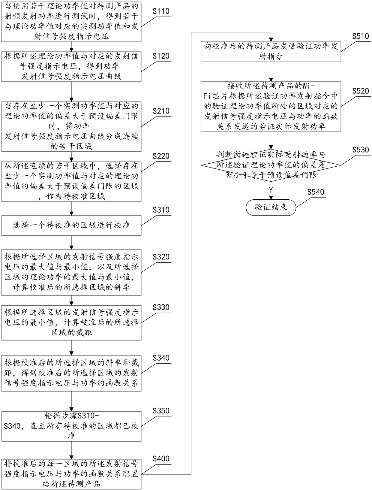
The invention provides a method and system for calibrating radio frequency transmitting power. The method comprises the following steps: step S100: when the radio frequency transmitting power of a to-be-tested product is tested by using a plurality of theoretical power values, obtaining a plurality of measured power values corresponding to the theoretical power values, and a power-transmitting signal strength indication voltage curve; step S200: when the deviation between at least one measured power value and the corresponding theoretical power value is greater than a preset deviation threshold, dividing the power-transmitting signal strength indication voltage curve into a plurality of continuous areas, and selecting a to-be-calibrated area; step S300: calibrating each to-be-calibrated area to obtain a functional relationship between a transmitting signal strength indication voltage and the power of each calibrated area; and step S400: configuring the functional relationship between the transmitting signal strength indication voltage and the power of each calibrated area to the to-be-tested product. By adoption of the method and system provided by the invention, the transmitting precision of small power can be improved, thereby ensuring that the high power and the small power transmitted by a Wi-Fi product are relatively accurate.

Description

technical field [0001] The invention relates to the radio frequency field, in particular to a method and equipment for calibrating radio frequency transmission power. Background technique [0002] At present, the RF transmitters of Wi-Fi products are relatively accurate when transmitting high power, but have large deviations when transmitting low power. It is impossible to ensure that the product is relatively accurate when transmitting high power and low power. But Wi-Fi products have the requirement of transmitting high power and low power. Taking Wi-Fi routing equipment as an example, when the user negotiates a lower modulation rate at a long distance, the routing equipment generally needs to use higher power transmission to improve the long-distance transmission capability. However, when the user uses it at a relatively short distance, it needs to use a lower transmission power to obtain a better Error Vector Magnitude (EVM for short). [0003] Wi-Fi chip power output ...

Claims


Application Information

Patent Timeline
Patent Type & Authority Applications(China)
IPC IPC(8): H04B17/13H04B17/10
CPCH04B17/102H04B17/13
Inventor 肖新武
Owner SICHUAN FEIXUN INFORMATION TECH CO LTD
Learn More