
The method of touch screen recognition touch

A touch screen, no-touch technology, applied in the input/output process of data processing, instruments, calculations, etc., can solve the problems of misjudgment, failure to consider the difference in distance, and the attenuation of the sensing electrode 500 sensing signal, so as to avoid misjudgment. Effect

Active Publication Date: 2020-11-24
TCL CHINA STAR OPTOELECTRONICS TECH CO LTD
View PDF8 Cites 0 Cited by
  • Summary
  • Abstract
  • Description
  • Claims
  • Application Information

AI Technical Summary

Problems solved by technology

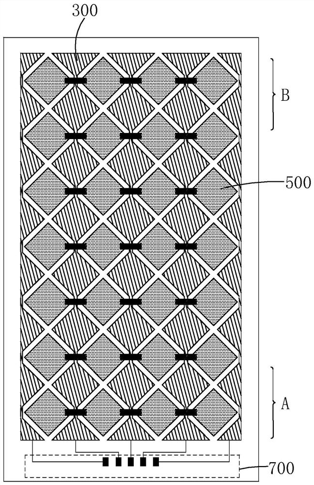
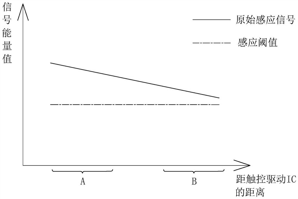
[0005] Please combine figure 1 and figure 2 , in the prior art, each touch sensing area in the touch screen uses the same sensing threshold to determine whether there is a touch, and does not take into account the different touch sensing areas and the touch driver IC 700 in the touch screen, especially the large-size touch screen. (used to generate the touch driving signal), and the touch driving signal is away from the end A (referred to as the near end) of the touch driving IC 700 from the touch electrode 300 close to the touch driving signal. One end B (referred to as the remote end) of the touch driving IC 700 will attenuate during transmission, and correspondingly, the sensing signal received by the sensing electrode 500 will also attenuate, and the resistance-capacitance (RC) of different touch sensing areas will change. There are certain differences, which will cause the original sensing signals of different touch sensing areas in the touch screen to be different
In this case, if the sensing signal changes in different touch sensing areas in the touch screen are still compared with the same sensing threshold when touching, there will be a problem of misjudgment, especially at the far end of the touch screen that cannot be sensitively and normally recognized. finger touch

Method used


Image

  • The method of touch screen recognition touch
  • The method of touch screen recognition touch
  • The method of touch screen recognition touch

Examples


no. 1 example

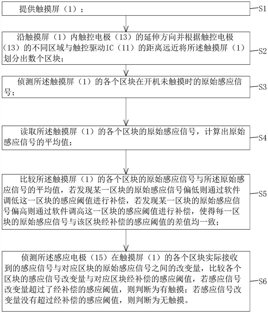
[0045] Please also see Figure 3 to Figure 5 , the first embodiment of the method for touch screen recognition touch of the present invention comprises the following steps:

[0046]Step S1, such as Figure 4 As shown, a touch screen 1 is provided.

[0047] The touch screen 1 includes a touch driver IC 11, a plurality of touch electrodes 13 arranged vertically, parallel to each other and electrically connected to the touch driver IC 11, and a plurality of touch electrodes 13 arranged laterally, parallel to each other and connected to the plurality of electrodes. The touch electrodes 13 are insulated from the crossing sensing electrodes 15 ; the touch driving IC 11 is located at one end of the touch electrodes 13 .

[0048] Wherein, the touch driver IC 11 is provided with a read-only memory ROM; the touch electrode 13 is used to transmit a touch driver signal of a fixed size sent by the touch driver IC 11, and the sensing electrode 15 is used for Receive induction signal.

...


PUM


Abstract

The invention provides a touch screen touch recognition method. The method includes: dividing a touch screen into a plurality of blocks, detecting original sensing signals of each block before power-on touch, and performing compensation of a sensing threshold of each block or reverse compensation of the original sensing signals of each block to realize uniformity of the original sensing signals ofeach block and sensing threshold difference of the corresponding block. Therefore, in subsequent detection of variation between practical received sensing signals of each block and the original sensing signals of the corresponding block and comparison of the sensing signal variation of each block with the corresponding sensing threshold, a comparison result of each block is insusceptible to differences of distances between different blocks and a touch drive IC, misjudgment can be avoided, and finger touch can be sensitively and normally recognized even from a far end of the touch screen.

Description

technical field [0001] The present invention relates to the technical field of touch control, in particular to a method for identifying touch on a touch screen. Background technique [0002] With the development of portable electronic display devices, a touch panel (Touch Panel) provides a new human-computer interaction interface, which can directly perform input through finger touch, and the operation is more intuitive and convenient. [0003] see figure 1 In the touch screen, there are usually a plurality of touch electrodes 300 arranged longitudinally and parallel to each other, and a plurality of sensing electrodes 500 arranged transversely and parallel to each other and insulated from the plurality of touch electrodes 300, wherein the touch The control electrode 300 is used for transmitting a touch driving signal with a fixed magnitude, and the sensing electrode 500 is used for receiving a sensing signal. When the user does not make a touch action, the sensing signal ...

Claims


Application Information

Patent Timeline
Patent Type & Authority Patents(China)
IPC IPC(8): G06F3/041
CPCG06F3/0416G06F3/0418
Inventor 陈蕾陈明暐康惠洋
Owner TCL CHINA STAR OPTOELECTRONICS TECH CO LTD
Learn More