Lubricating device for maintaining equipment

A technology for lubricating equipment and maintenance equipment, applied in mechanical equipment, transmission parts, gear lubrication/cooling, etc., can solve problems such as operator personal injury, waste, safety hazards, etc., to avoid personal injury, avoid excessive or excessive Less, avoid the effect of position offset

Inactive Publication Date: 2018-08-14
重庆春信实业有限公司
View PDF7 Cites 0 Cited by
  • Summary
  • Abstract
  • Description
  • Claims
  • Application Information

AI Technical Summary

Problems solved by technology

Manual refueling equipment is small and easy to operate, but requires physical strength of the operator; pneumatic refueling equipment is labor-saving to operate, but the equipment is heavy and limited by the site
Both types of filling equipment cannot accurately control the filling volume, and the lubrication effect cannot be achieved when the filling volume is small. When the filling volume is large, it will not only cause waste, but may also corrode equipment parts or affect product quality. In addition, manual operation Not only the filling time period is not easy to guarantee, but also there are potential safety hazards in the lubricating oil filling operation. In the process of operation, work-related injuries or equipment accidents are easy to occur, which will bring personal injury to the operator and cause economic losses to the enterprise.

Method used


Image

  • Lubricating device for maintaining equipment
  • Lubricating device for maintaining equipment

Examples


Embodiment

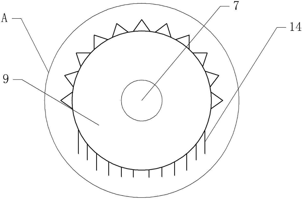
[0022] as attached figure 1 As shown, a lubricating device for maintaining equipment includes a box body 1, and two clamping blocks 6 are slidably connected to the right side of the box body 1, and the two clamping blocks 6 are respectively located at the upper and lower parts of the box body 1 and are both Can slide along the vertical direction of the box body 1. A sliding shaft 5 is fixed on the box body 1 , and several limiting holes and pins 17 are provided on the sliding shaft 5 . When the clamping block 6 slides onto the sliding shaft 5 that can extend the sliding distance of the clamping block 6 , the pin 17 can be inserted into the limiting hole to limit the clamping block 6 .

[0023] The clamping block 6 is provided with an oil chamber 13 , a servo motor 7 , an incomplete gear 9 and a button switch 8 . The servo motor 7 is fixed on the right side of the clamping block 6 by fastening bolts, and the servo motor 7 is electrically connected with a button switch 8 fixed...


PUM


Abstract

The invention relates to the technical field of equipment maintenance, and discloses a lubricating device for maintaining equipment. The lubricating device comprises a box body, the box body is connected with two clamping blocks in a sliding mode, and an oil cavity, a servo motor, an incomplete gear and a button switch are formed in each clamping block; each incomplete gear is rotationally connected with the corresponding clamping block, and each incomplete gear comprises a smooth part and a toothed part, wherein the smooth part and the toothed part can be positioned in the corresponding oil cavity; each servo motor is fixed on the corresponding clamping block and is electrically connected with the corresponding button switch, and each button switch is fixed to the side close to the corresponding servo motor; an output shaft of each servo motor is fixedly connected with the corresponding incomplete gear, and an ejector rod which is in sliding connection with the box body is arranged between the two clamping blocks; the two ends of the ejector rod penetrate through the box body, and a limiting block is arranged at the end, away from the clamping blocks, of the ejector rod; the end,close to the clamping blocks, of the ejector rod is sleeved with a drainage groove, and a sliding plate positioned in the box body is fixed between the two ends of the ejector rod; and an oil channelcommunicating with the drainage groove is formed in the box body, and a gap is formed in the ejector rod. The lubricating device is simple in structure, and a lubricant is convenient to inject duringmaintaining the equipment.

Description

technical field [0001] The invention relates to the technical field of equipment maintenance, in particular to a lubricating device for maintaining equipment. Background technique [0002] Lubricants are lubricating media used to reduce the frictional resistance of friction pairs of mechanical devices and slow down their wear. The lubricant can also cool the airway, clean and prevent pollution on the friction pair. Especially in mechanical equipment, lubricants are required to maintain the mechanical equipment to ensure the performance of the mechanical equipment. [0003] At present, the lubricating oil of mechanical equipment is generally added to the chain and gear, and the manual operation mode is adopted, that is, according to the period required by the standard, the chain or gear parts are filled one by one through a manual oil gun (oiler) or pneumatic filling equipment. Oil operation. Manual refueling equipment is small in size and easy to operate, but requires phy...

Claims


Application Information

Patent Timeline
IPC IPC(8): F16H57/04
CPCF16H57/0467
Inventor 李小琼
Owner 重庆春信实业有限公司
Why Eureka
Try Eureka