
Lifting frame for detection jig

A technology for testing jigs and lifting frames, which is applied in lifting frames, lifting devices, etc., can solve the problems of increasing manual labor, people are prone to fatigue, etc., and achieve the effect of improving testing comfort and reducing fatigue

Inactive Publication Date: 2018-08-14
DONGGUAN TIANHE ELECTROMECHANICAL DEV CO LTD
View PDF5 Cites 3 Cited by
  • Summary
  • Abstract
  • Description
  • Claims
  • Application Information

AI Technical Summary

Problems solved by technology

[0002] Existing detection fixtures are generally directly fixed on the top plate of the frame for detection. However, due to the different heights of the users, the height of the frame is fixed, so that taller users need to bend down for detection, making it easy for people to detect. Fatigue, increased manual labor

Method used


Image

  • Lifting frame for detection jig
  • Lifting frame for detection jig

Examples


Embodiment Construction

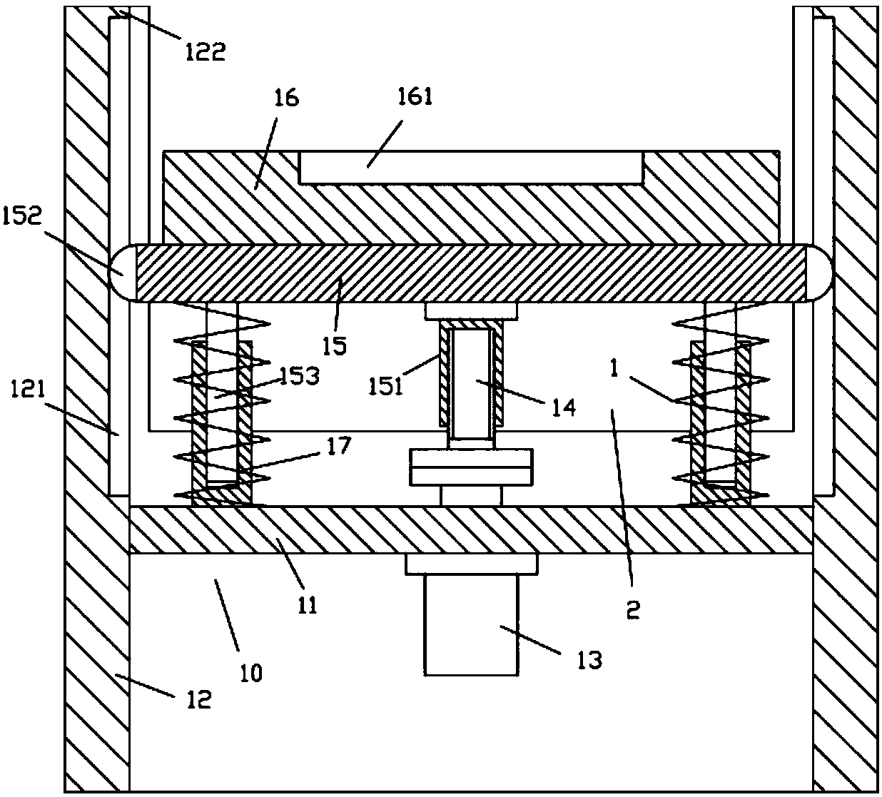
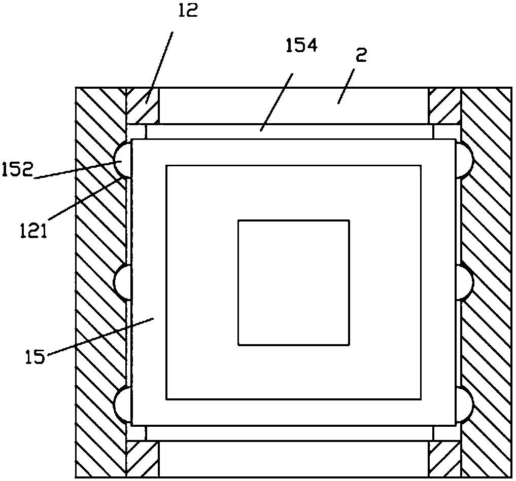
[0015] Examples, see e.g. Figures 1 to 2 As shown, a lifting frame for a detection fixture includes a frame 10, and the frame 10 includes a main base plate 11, the four side walls of the main base plate 11 are fixed with vertical support plates 12, and the side walls of the main base plate 11 Fixed on the inner side wall of the middle part of the vertical support plate 12, the bottom surface of the middle part of the main base plate 11 is fixed with a lifting motor 13, the output shaft of the lifting motor 13 passes through the main base plate 11 and is connected with a vertical screw rod 14 through a coupling, and the lifting plate 15 is located above the main bottom plate 11, the bottom surface of the middle part of the lifting plate 15 is fixed with a vertical screw sleeve 151, and the vertical screw rod 14 is screwed in the vertical screw sleeve 151;

[0016] A plurality of hemispherical self-lubricating blocks 152 are fixed on the left and right side walls of the lifting...


PUM


Abstract

The invention discloses a lifting frame for a detection jig. The lifting frame for the detection jig comprises a rack. The rack comprises a main bottom plate. Four side walls of the main bottom plateare all fixedly provided with vertical supporting plates. The side walls of the main bottom plate are fixed to the middle inner side walls of the vertical supporting plates. The bottom of the middle of the main bottom plate is fixedly provided with a lifting motor. An output shaft of the lifting motor penetrates the main bottom plate and is connected with a vertical screw through a coupler. A lifting plate is located above the main bottom plate, the bottom of the middle of the lifting plate is fixedly provided with a vertical thread sleeve, and the vertical screw is screwed into the vertical thread sleeve. The left side wall and the right side wall of the lifting plate are fixedly provided with a plurality of semispherical self-lubrication blocks. The inner side wall of the left vertical supporting plate and the inner side wall of the right vertical supporting plate are provided with a plurality of vertical sliding grooves which are parallel, and the semispherical self-lubrication blocks are inserted into the vertical sliding grooves. According to the lifting frame for the detection jig, the height of the lifting plate can be adjusted so that the detection using requirement can bemet for different statures of users, and therefore the fatigue of the users is reduced, and the detection comfort is improved.

Description

Technical field: [0001] The invention relates to the technical field of mechanical testing equipment, and more specifically relates to a lifting frame for testing jigs. Background technique: [0002] Existing detection fixtures are generally directly fixed on the top plate of the frame for detection. However, due to the different heights of the users, the height of the frame is fixed, so that taller users need to bend down for detection, making it easy for people to detect. Fatigue increases the amount of manual labor. Invention content: [0003] The purpose of the present invention is to overcome the deficiencies of the prior art and provide a lifting frame for testing fixtures, which can adjust the height of the lifting plate to meet the needs of users of different heights for testing, thereby reducing user fatigue and improving detection. comfort. [0004] The scheme that the present invention solves described technical problem is: [0005] A lifting frame for a dete...

Claims


Application Information

Patent Timeline
Patent Type & Authority Applications(China)
IPC IPC(8): B66F7/14B66F7/28
CPCB66F7/14B66F7/28
Inventor 林庆芳
Owner DONGGUAN TIANHE ELECTROMECHANICAL DEV CO LTD
Learn More