Screw lifting frame for detection jig
A technology for detecting jig and lifting frame, applied in the direction of lifting frame, lifting device, etc., can solve the problems of easy fatigue and increase the amount of manual labor, and achieve the effect of reducing fatigue and improving detection comfort.
- Summary
- Abstract
- Description
- Claims
- Application Information
AI Technical Summary
Problems solved by technology
Method used
Image
Examples
Embodiment Construction
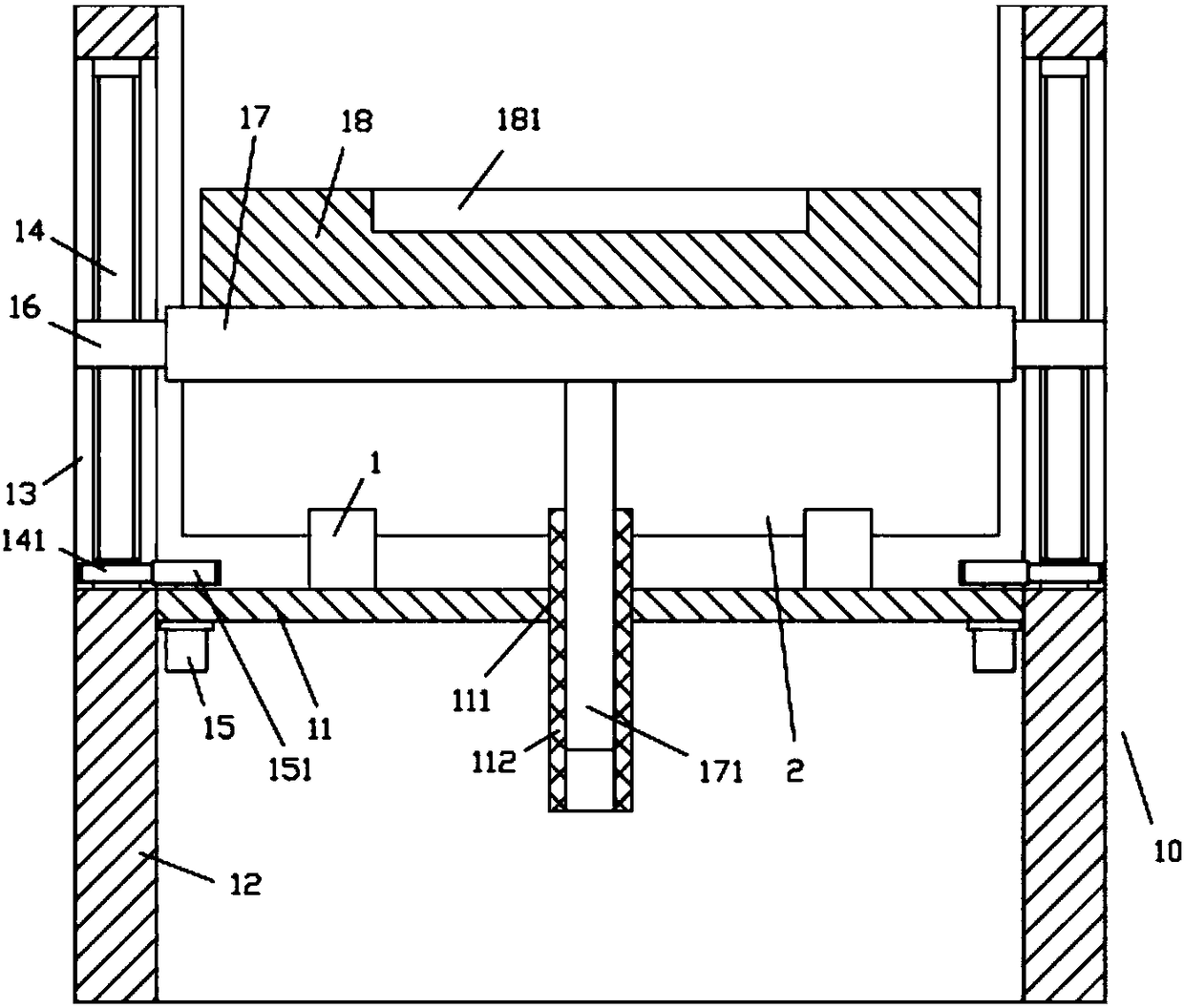
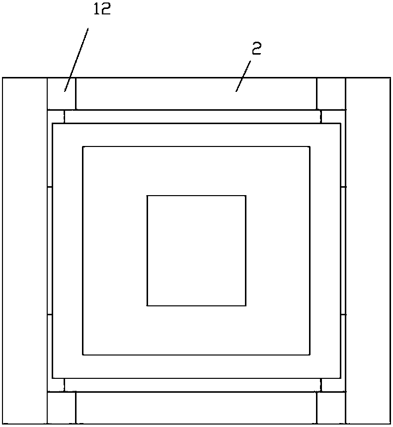
[0014] Examples, see e.g. Figures 1 to 2 As shown, a screw lifting frame for a detection fixture includes a frame 10, and the frame 10 includes a main base plate 11, the four side walls of the main base plate 11 are fixed with vertical support plates 12, and the side walls of the main base plate 11 The wall is fixed on the inner side wall of the middle part of the vertical support plate 12, and the upper part of the left and right vertical support plates 12 is formed with a side vertical through groove 13, and the vertical screw rod 14 is in the side vertical through groove 13, and the vertical screw rod 14 The two ends of the two ends are hinged on the top and the bottom of the vertical through groove 13, the bottom of the vertical screw rod 14 is fixed with a transmission gear 141, the left and right sides of the main base plate 11 are fixed with a drive motor 15, and the drive motor 15 The output shaft passes through the main base plate 11 and is fixed with a driving gear ...
PUM
 Abstract
Description
Claims
Application Information
 - R&D Engineer
- R&D Manager
- IP Professional
- Industry Leading Data Capabilities
- Powerful AI technology
- Patent DNA Extraction
Browse by: Latest US Patents, China's latest patents, Technical Efficacy Thesaurus, Application Domain, Technology Topic, Popular Technical Reports.
© 2024 PatSnap. All rights reserved.Legal|Privacy policy|Modern Slavery Act Transparency Statement|Sitemap|About US| Contact US: help@patsnap.com


