
Position accuracy measuring device and method for manipulator arm

A robotic arm, precision measurement technology, applied in measuring devices, manipulators, program-controlled manipulators, etc., can solve the problems of low accuracy of robotic arms and high price of laser trackers, and achieve good practicability, low cost, and easy development. Effect

Inactive Publication Date: 2018-08-14
DALIAN UNIV OF TECH
View PDF4 Cites 18 Cited by
  • Summary
  • Abstract
  • Description
  • Claims
  • Application Information

AI Technical Summary

Problems solved by technology

However, due to too many joints of the robotic arm, multiple errors are accumulated and transmitted, resulting in generally low precision of the robotic arm.
At present, the correction of the spatial position accuracy of the mechanical arm is based on the five-point position method on the slope specified in the international standard ISO9283 "Operational Industrial Robot Performance Standards and Detection Methods", but it cannot realize the real-time detection and accuracy of the mechanical arm accuracy. compensate
The existing robotic arm accuracy measurement devices are mainly laser trackers, and laser trackers are expensive

Method used


Image

  • Position accuracy measuring device and method for manipulator arm
  • Position accuracy measuring device and method for manipulator arm
  • Position accuracy measuring device and method for manipulator arm

Examples


Embodiment Construction

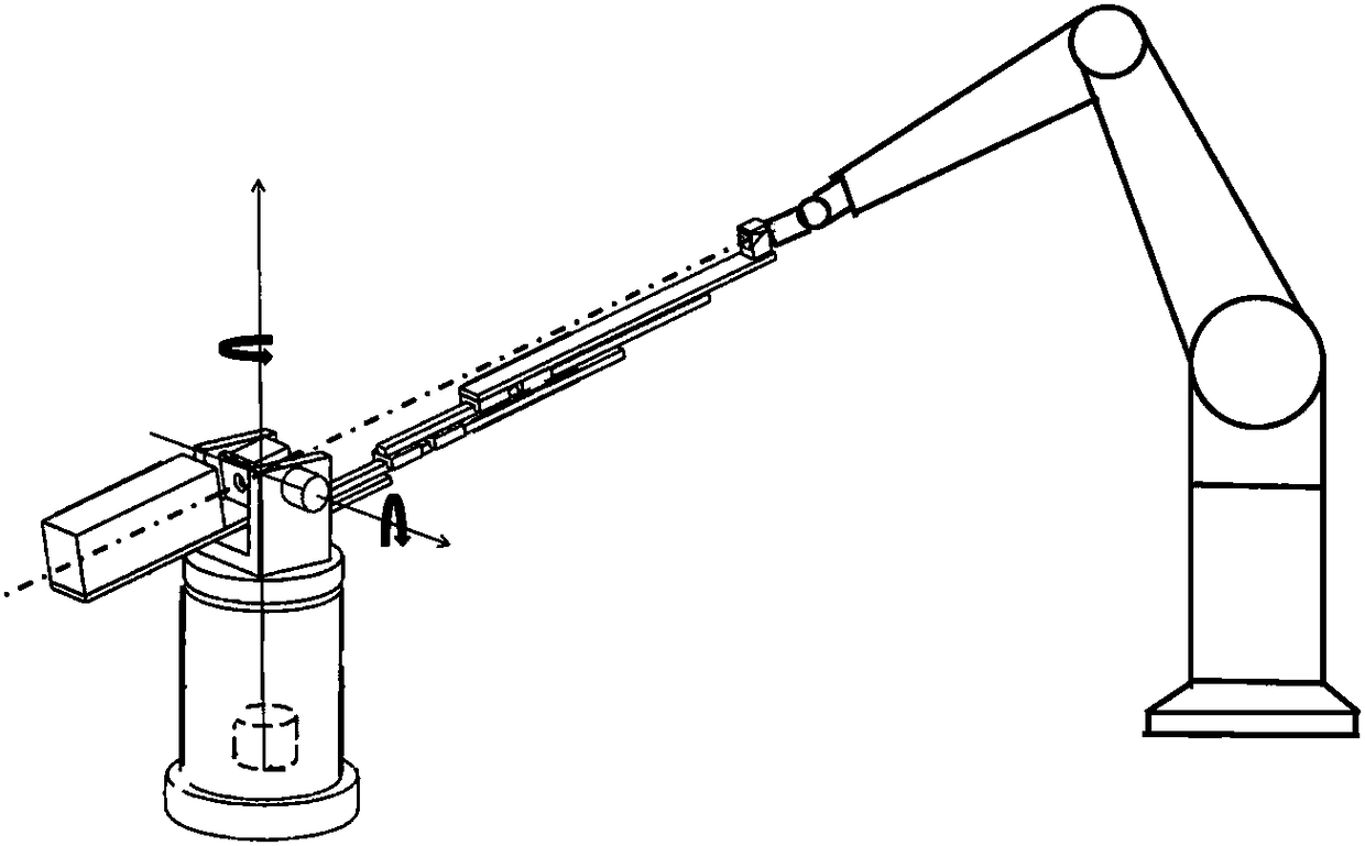
[0016] The main structure of the innovative "passive three-dimensional spherical coordinate mechanism" is as follows: (1) two turntables orthogonal to each other, including an azimuth turntable and a pitch turntable, each turntable is equipped with an angle encoder to read the actual angle; (2) Radial telescopic mechanism, which consists of two slide rails and a traction plate that pass through the rotation centers of the two turntables and are perpendicular to the pitch angle rotation axis, and the actual length of the telescopic mechanism is read by a laser interferometer fixed on the other side of the turntable center . The movement of each structure is described in detail below:

[0017] Such as figure 1 As shown, the azimuth turntable 13 is placed on the ground, and the coordinate system (X, Y, Z) of the three-dimensional spherical coordinate mechanism is provided. The rotating shaft 11 rotates 360° around the Z axis, and the azimuth θ is provided by the azimuth encoder...


PUM


Abstract

The invention belongs to the field of dynamic trajectory accuracy calibration of manipulator arms, and provides a position accuracy measuring device and method for a manipulator arm. The dynamic trajectory error of the manipulator arm is measured by means of two orthogonal turntables and a radial telescopic mechanism passing through two rotating centers. A precise standard steel ball fixed at theend point of the radial telescopic mechanism is attracted to a magnetic ball seat fixed at the end point of the manipulator arm, the spatial position coordinates (X, Y, Z) of the end point of the manipulator arm are obtained by coordinate transformation of the steel ball coordinates (R, theta, phi) on a three-dimensional spherical coordinate mechanism, and the position error of the end point of the mechanical arm can be obtained by subtracting the coordinate position and the motion command position of the manipulator arm. A three-dimensional spherical coordinate system is formed by integratingan azimuth angle, a pitch angle and a radial length, and the precision of the spherical coordinate mechanism is higher than that of the manipulator arm. The position accuracy measuring device has portability, low cost, good practicability and easy product development, and the real-time measurement of the error of the manipulator arm error can be completed.

Description

technical field [0001] The invention belongs to the field of dynamic track precision calibration of a mechanical arm, and relates to a measuring device and method for a mechanical arm. Background technique [0002] Among machines with a motion coordinate system, the robotic arm is the only automated mechanism capable of rapid three-dimensional motion. However, due to too many joints of the robotic arm, multiple errors are accumulated and transmitted, resulting in generally low precision of the robotic arm. At present, the correction of the spatial position accuracy of the mechanical arm is based on the five-point position method on the slope specified in the international standard ISO9283 "Operational Industrial Robot Performance Standards and Detection Methods", but it cannot realize the real-time detection and accuracy of the mechanical arm accuracy. compensate. The existing robotic arm accuracy measurement devices are mainly laser trackers, but the laser trackers are ex...

Claims


Application Information

Patent Timeline
Patent Type & Authority Applications(China)
IPC IPC(8): B25J19/00G01B11/00G01B21/00
CPCB25J19/0095G01B11/002G01B21/00B25J9/045B25J9/1692G01B11/026
Inventor 范光照娄志峰田雨辰徐良
Owner DALIAN UNIV OF TECH
Learn More