A rock impact test device

A technology of collision test and rock, which is applied in the direction of testing the strength of materials with one-time impact force, can solve the problems of inability to realize single-point impact test of rock blocks, small speed range, immature technology, etc., and achieve single-point and double-point collision Test and realize the effect of high-precision control

Inactive Publication Date: 2019-08-20
WUHAN UNIV
View PDF7 Cites 0 Cited by
  • Summary
  • Abstract
  • Description
  • Claims
  • Application Information

AI Technical Summary

Problems solved by technology

At present, the test devices for studying the dynamic characteristics of rocks are mainly Hopkins compression rods and drop weight impact devices, but these devices are loaded at both ends (or two points) at the same time, and cannot achieve single-point impact tests on rock blocks.
At present, there are few researches on the accelerated collision device of rock samples at home and abroad, and the technology is not mature, especially the speed control accuracy of rock samples is poor, and the speed range that can be realized is small

Method used


Image

  • A rock impact test device
  • A rock impact test device
  • A rock impact test device

Examples


Embodiment Construction

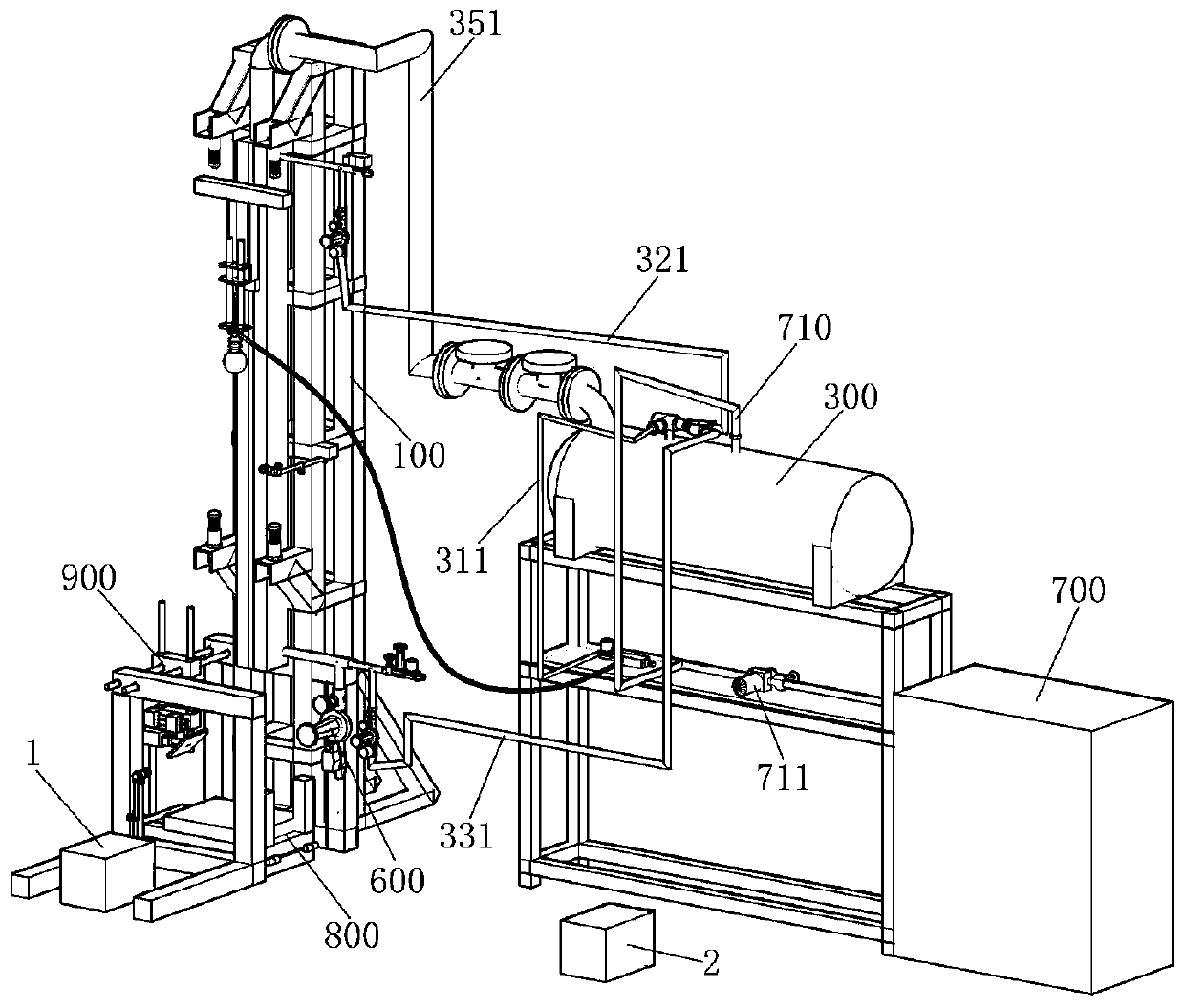
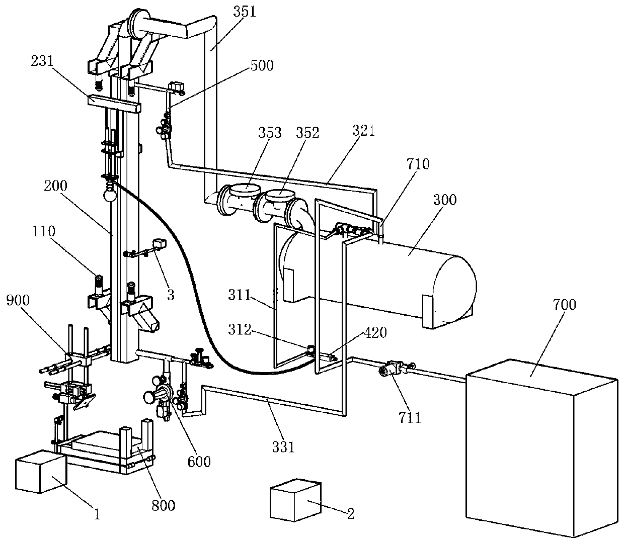
[0044] Such as Figure 1 to Figure 8 As shown, in order to show the main structure clearly, remove figure 1 The support structure in part gets figure 2 . A rock impact test device, characterized in that it includes a frame 100, a rodless cylinder 200, an air storage tank 300, a vacuum holding assembly, an upper intake and exhaust assembly 500, a lower intake and exhaust assembly 600, an air compressor 700, a collision The component 800, the first photoelectric sensor 3, the high-speed camera 1, and the controller 2 are characterized in that,

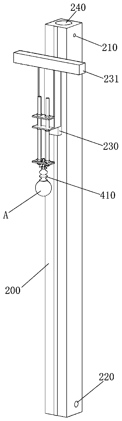
[0045] The rodless cylinder 200 is vertically and fixedly arranged on the frame 100, and the side walls at the upper and lower ends thereof respectively have an upper intake and exhaust port 210 and a lower intake and exhaust port 220;

[0046] The air storage tank 300 is provided with a tank intake pipe 340 and a tank air supply pipe, and the tank air supply pipe is provided with a first branch pipe 310, a second branch pipe 320 and...


PUM


Abstract

The invention provides a rock collision test device, which comprises a rack, a rodless cylinder, a gas storage tank, a vacuum holding assembly, an upper intake and exhaust assembly, a lower intake andexhaust assembly, an air compressor, a collision assembly, a first photoelectric sensor, a high-speed camera, a controller, and also includes a rebound protection assembly. The rock collision test device provided by the invention utilizes the rodless cylinder, the upper intake and exhaust assembly and the lower intake and exhaust assembly to realize adjustment of rock collision velocity, and canacquire a high collision velocity, utilizes the rebound protection assembly to strictly control the number of times of collision, utilizes the collision assembly to realize adjustment of the collisionangle, utilizes the vacuum holding assembly to hold spheres and cylinder impact blocks of various sizes, and utilizes an electrical control structure to achieve high precision control, and has the characteristics of simple operation and strong practicability.

Description

technical field [0001] The invention belongs to the field of rock impact tests, in particular to a rock impact test device. Background technique [0002] Rock impact test is one of the basic methods to study rock dynamic behavior. At present, the test devices for studying the dynamic characteristics of rocks are mainly Hopkins compression rods and drop weight impact devices, but these devices are loaded at both ends (or two points) at the same time, and cannot realize single-point impact tests on rock blocks. At present, there are few researches on the acceleration and collision device of rock samples at home and abroad, and the technology is not mature, especially the speed control accuracy of rock samples is poor, and the speed range that can be realized is small. Contents of the invention [0003] In view of the above technical problems, the present invention provides a rock impact test device with adjustable impact speed. [0004] In order to solve the problems of th...

Claims


Application Information

Patent Timeline
Patent Type & Authority Patents(China)
IPC IPC(8): G01N3/30
Inventor 曾亚武叶阳
Owner WUHAN UNIV
Why Eureka
Try Eureka