
an ice cube

A technology of ice cylinder and installation cylinder, which is applied in the direction of ice making, ice making, ice storage/distribution, etc. It can solve the problems of cumbersome ice making process and achieve the effect of simple and fast ice making process

Active Publication Date: 2019-09-13
凤阳县易天成模具有限公司
View PDF1 Cites 0 Cited by
  • Summary
  • Abstract
  • Description
  • Claims
  • Application Information

AI Technical Summary

Problems solved by technology

[0003] The purpose of the present invention is to provide an ice-making cylinder to solve the problem in the prior art that the ice-making cylinder needs to be connected to the bottom plate through ice, which leads to a cumbersome ice-making process.

Method used


Image

  • an ice cube
  • an ice cube
  • an ice cube

Examples


Embodiment Construction

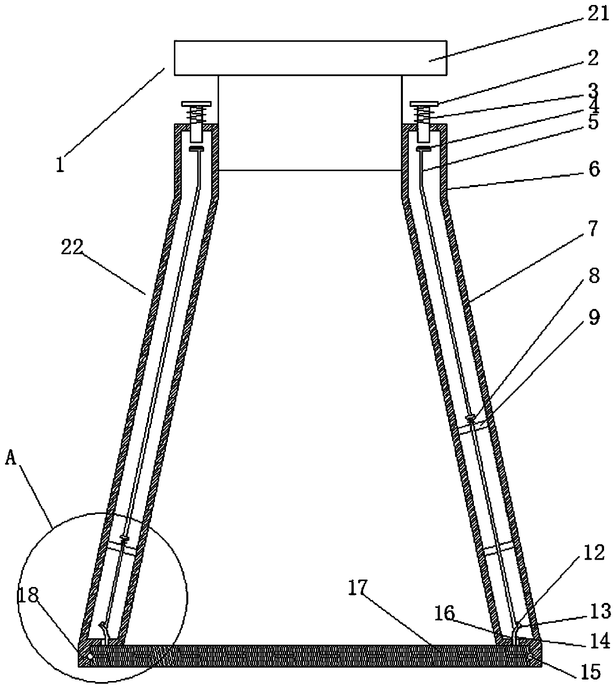
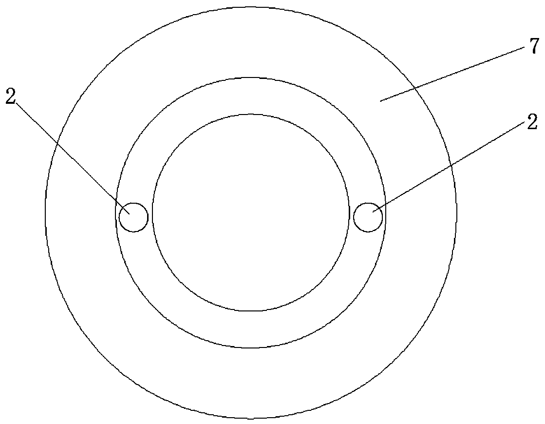
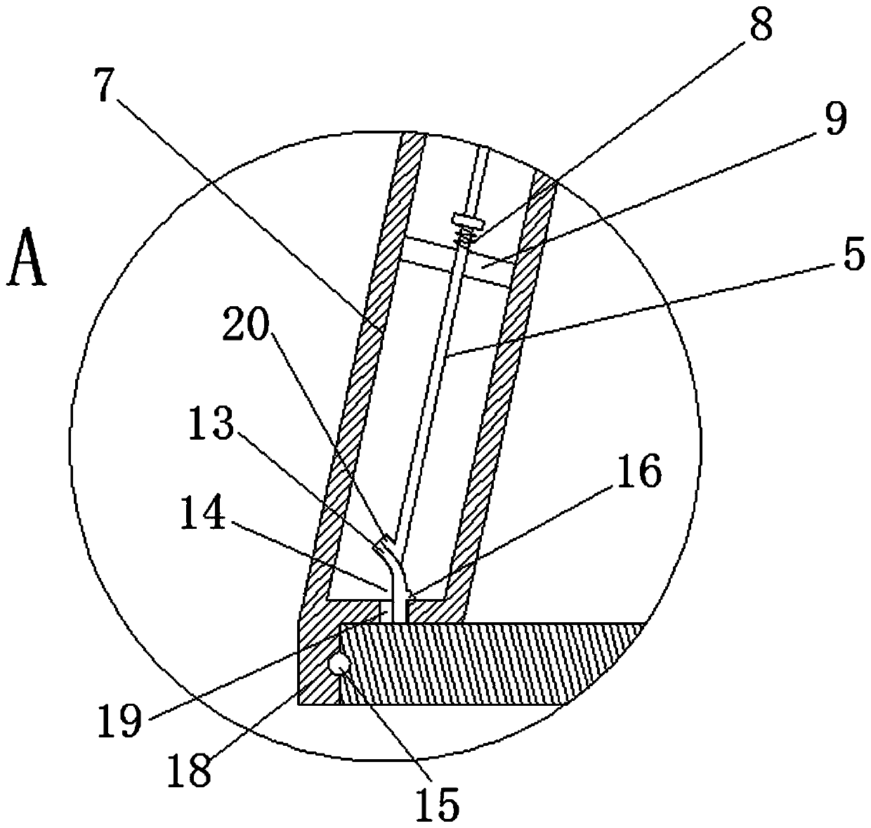
[0015] An example of an ice cube Figure 1~4 Shown: including the ice maker body 22, the ice maker body 22 is a hollow structure filled with thermal insulation material, the item 1 in the figure indicates the bucket cover 1 used with the ice maker when in use, and the item 17 indicates the lid 1 used in conjunction with the ice maker when in use. The bottom plate used in conjunction with the cylinder, the ice-making cylinder includes a cylindrical cylinder section 6 and a conical cylinder section 7 arranged at the lower end of the cylindrical cylinder section, the cavity diameter of the conical cylinder section 7 is small at the top and large at the bottom. The inner wall of the cylindrical barrel section has connecting threads, and the cap 1 is threadedly connected with the connecting threads. Bottom plate 17 is made of heat-conducting material, and the bottom plate of the present invention is made of copper material, two elastic hooks 14 arranged at intervals along the circu...


PUM


Abstract

The invention relates to an ice making drum which comprises an ice making drum body. A bottom plate mounting drum is arranged at the lower end of the ice making drum body, and is provided with a mounting drum inner wall hermetically matched with the periphery of a corresponding bottom plate by means of a seal ring. Hook penetration holes for allowing elastic hooks on the bottom plate to pass are formed in the bottom of the ice making drum body and on the inner side of the bottom plate mounting drum. A push rod device, which can move in the up-and-down direction to push the upper ends of the elastic hooks to separate hook parts of the elastic hooks from the ice making drum body, is arranged on the ice making drum. Through the adoption of the ice making drum, the problem that in the prior art, an ice making drum and a bottom plate need to be in frozen connection in a refrigerator in advance, so that the ice making process is tedious is solved.

Description

technical field [0001] The invention relates to an ice-making cylinder in daily necessities. Background technique [0002] An ice tray for making ice is usually included in the purchased refrigerator, and the ice tray is an ice-making device. Existing ice-making devices such as the "household ice-making cup" disclosed in Chinese patent CN105066541B include a cup body and a cup cover. The cup body includes a cone-shaped cylinder, that is, an ice-making cylinder and a bottom plate. And the cup cover has a thermal insulation structure. The cup cover is threadedly connected with the cup body. When in use, the bottom plate absorbs the heat of the water in the gap between it and the cone, and freezes the water in the gap, so that the bottom plate and the cone can be frozen together, so that the water in the cone cannot leak out . That is to say, the bottom plate is connected together through the ice rain cone formed between the bottom plate and the cone. out of the barrel. T...

Claims


Application Information

Patent Timeline
Patent Type & Authority Patents(China)
IPC IPC(8): F25C1/24F25C5/04
Inventor 李晓丽
Owner 凤阳县易天成模具有限公司
Learn More