
Large-caliber special pipeline processing device

A processing device and large-diameter technology, applied in positioning devices, metal processing equipment, metal processing machinery parts, etc., can solve the problems of manual cutting, such as high labor intensity, troublesome operation, and affecting pipelines, so as to improve cutting efficiency and make adjustments fast and convenient , the effect of strong flexibility

Pending Publication Date: 2018-08-10
贵州枫叶管业有限公司
View PDF0 Cites 3 Cited by
  • Summary
  • Abstract
  • Description
  • Claims
  • Application Information

AI Technical Summary

Problems solved by technology

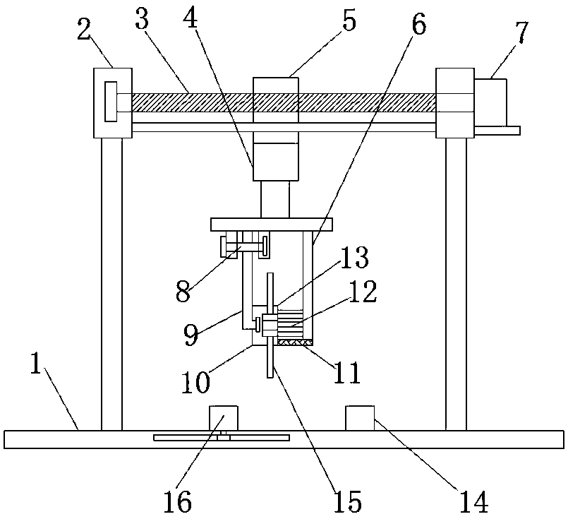
[0002] There are many processes in the processing of pipelines, and the stability of each process affects the quality of the pipelines, especially large-diameter special pipelines, which are mostly used in gas pipelines and chemical pipelines, etc. Large-diameter pipelines are often used in processing Cutting device, in the current cutting and processing operations, in addition to mechanical cutting, the special pipes with small diameters are also cut manually. Manual cutting is labor-intensive and low-precision, and is suitable for cutting operations with low requirements. The pipe must be cut with a cutting device. However, the existing cutting device generally has a fixed blade cutting position. It is necessary to continuously adjust the cutting pipe during processing. During the adjustment, the fixed pipe needs to be continuously loosened and then fixed at the specified position. , the operation is more troublesome and takes a certain amount of time, so we propose a large-diameter special pipe processing device

Method used


Image

  • Large-caliber special pipeline processing device
  • Large-caliber special pipeline processing device
  • Large-caliber special pipeline processing device

Examples


Embodiment Construction

[0019] The following will clearly and completely describe the technical solutions in the embodiments of the present invention with reference to the accompanying drawings in the embodiments of the present invention. Obviously, the described embodiments are only some, not all, embodiments of the present invention.

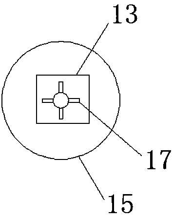
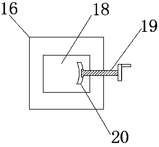
[0020] refer to Figure 1-3 , a large diameter special pipe processing device, including a base plate 1, a clamping block 16 is slidably connected to the top of the base plate 1, a limiting block 14 is provided on one side of the clamping block 16, and the limiting block 14 is fixed on the base plate 1, and the base plate 1 Four evenly distributed and vertically arranged support rods are fixed on the top of the support rod, and two symmetrically arranged cross columns 2 are fixed on the top of the support rod, and the cross columns 2 are all located between the two support rods and are located between the clamping block 16 and the On both sides of the limit block 14 ...


PUM


Abstract

The invention discloses a large-caliber special pipeline processing device which comprises a base plate. The top end of the base plate is connected with a clamping block in a sliding mode. A limitingblock is arranged on one side of the clamping block and is further fixed to the base plate. Four supporting rods which are evenly distributed and further vertically arranged are fixed to the top end of the base plate. Two symmetrical transverse pillars are fixed to the top ends of the supporting rods. The transverse pillars are both located between every two supporting rods and are further disposed on the two sides of the position where the clamping block and the limiting block are away from each other. A horizontal lead screw is connected between the two transverse pillars in a rotating mode.A first motor is arranged on one side of one of the transverse pillars, and an output shaft of the first motor is connected to one end of the lead screw. The lead screw is connected with a threaded block in a threaded mode, and a horizontal guide rod is arranged between the two transverse pillars. The large-caliber special pipeline processing device is simple in structure and reasonable in design, multi-section processing of pipelines can be achieved, there is no need to adjust the pipeline positions repeatedly, and cutting efficiency is improved; and meanwhile, the pipelines of different lengths can be processed, flexibility is high and the large-caliber special pipeline processing device is suitable for being popularized.

Description

technical field [0001] The invention relates to the technical field of pipe processing devices, in particular to large-diameter special pipe processing devices. Background technique [0002] There are many processes in the processing of pipelines, and the stability of each process affects the quality of the pipelines, especially large-diameter special pipelines, which are mostly used in gas pipelines and chemical pipelines, etc. Large-diameter pipelines are often used in processing Cutting device, in the current cutting and processing operations, in addition to mechanical cutting, the special pipes with small diameters are also cut manually. Manual cutting is labor-intensive and low-precision, and is suitable for cutting operations with low requirements. The pipe must be cut with a cutting device. However, the existing cutting device generally has a fixed blade cutting position. It is necessary to continuously adjust the cutting pipe during processing. During the adjustment,...

Claims


Application Information

Patent Timeline
IPC IPC(8): B23Q3/06B23Q1/25B23Q3/12B23Q3/00
CPCB23Q1/25B23Q3/00B23Q3/06B23Q3/062B23Q3/064B23Q3/12Y02P70/10
Inventor 徐建良王新路徐海江廖群朱杨洁
Owner 贵州枫叶管业有限公司
Learn More