
Steel pipe cutting device and cutting method thereof

A technology for cutting devices and steel pipes, applied in the direction of pipe shearing devices, shearing devices, shearing machine equipment, etc., can solve the problems that the steel pipe diameter and cutting length can not be adjusted at the same time, and the cutting machine has a single function, so as to achieve a simple cutting method, Strong practicability and wide application range

Pending Publication Date: 2018-08-10
TIANJIN PIPELINE ENG GROUP
View PDF10 Cites 5 Cited by
  • Summary
  • Abstract
  • Description
  • Claims
  • Application Information

AI Technical Summary

Problems solved by technology

[0004] In view of this, the present invention aims to propose a steel pipe cutting device and its cutting method to solve the technical problem that the cutting machine has a single function and cannot simultaneously satisfy the steel pipe diameter and cutting length adjustment.

Method used


Image

  • Steel pipe cutting device and cutting method thereof
  • Steel pipe cutting device and cutting method thereof
  • Steel pipe cutting device and cutting method thereof

Examples


Embodiment Construction

[0032] It should be noted that, in the case of no conflict, the embodiments of the present invention and the features in the embodiments can be combined with each other.

[0033] In describing the present invention, it should be understood that the terms "center", "longitudinal", "transverse", "upper", "lower", "front", "rear", "left", "right", The orientations or positional relationships indicated by "vertical", "horizontal", "top", "bottom", "inner", "outer", etc. are based on the orientation or positional relationships shown in the drawings, and are only for the convenience of describing the present invention Creation and simplification of description, rather than indicating or implying that the device or element referred to must have a specific orientation, be constructed and operate in a specific orientation, and therefore should not be construed as limiting the invention. In addition, the terms "first", "second", etc. are used for descriptive purposes only, and should no...


PUM

PropertyMeasurementUnit
angleaaaaaaaaaa

Abstract

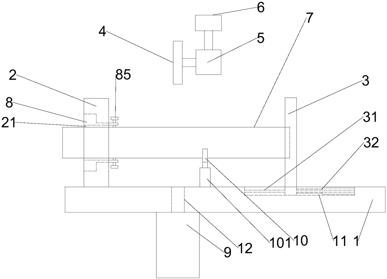
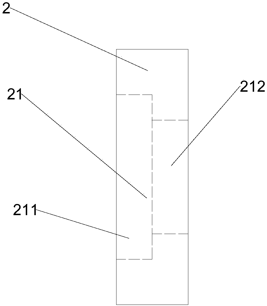
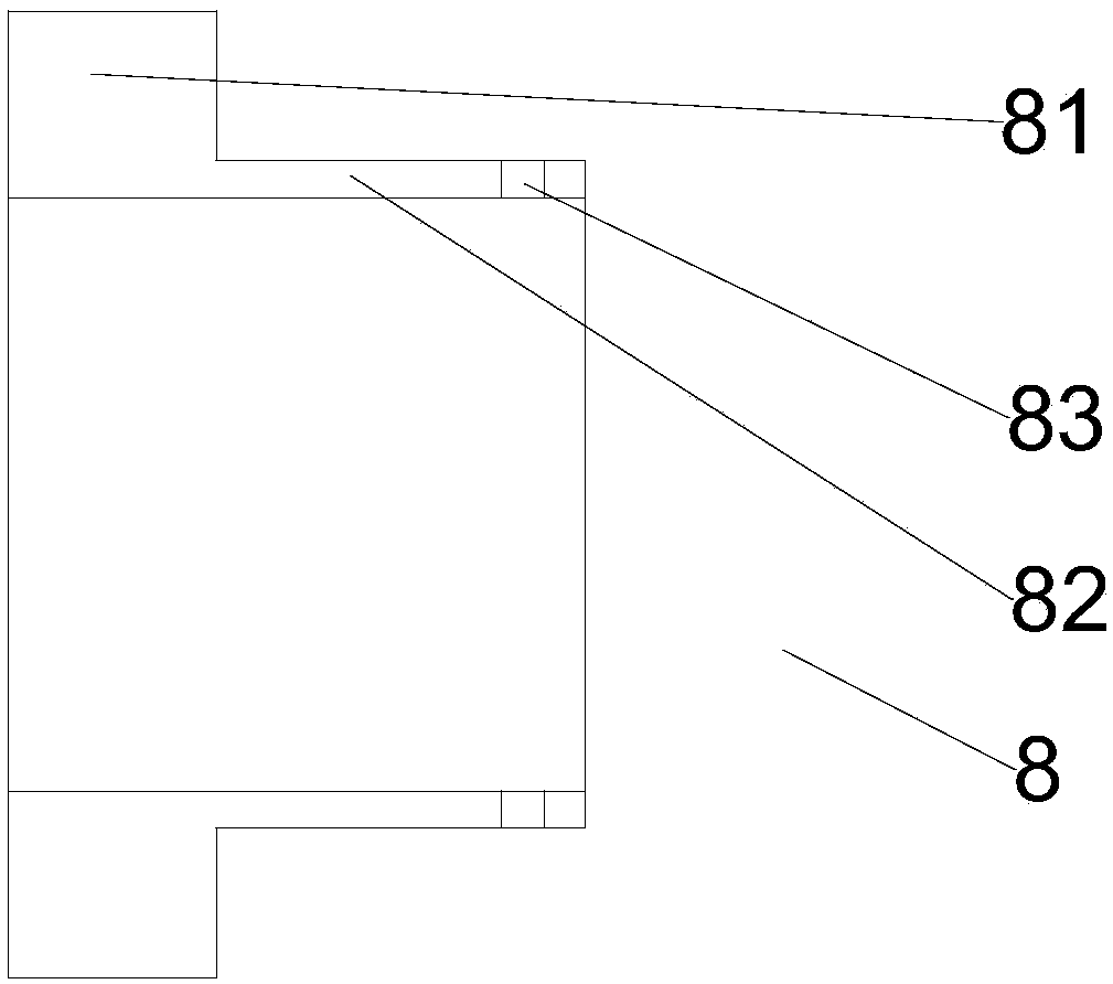
The invention provides a steel pipe cutting device and a cutting method thereof. The device comprises a workbench, a fixing clamping plate and an adjustment clamping plate are oppositely arranged on the workbench, and a mounting hole is formed in the fixing clamping plate; an adjustable mold for supporting a steel pipe to be cut is coaxially arranged in the mounting hole, a sliding groove is formed in the workbench, and two guide holes are formed in the bottom of the adjustment clamping plate; a guide rod penetrates through the guide holes, the two ends of the guide rod are fixed to the side wall of the sliding groove separately, and the guide rod is parallel to the axis of the mounting hole; the adjustment clamping plate is connected with a first retractable rod, the first retractable rodis parallel to the guide rod, and multiple annular grooves which are coaxial with the mounting hole are formed in the surface of the adjustment clamping plate opposite to the fixing clamping plate; acutter is arranged over the steel pipe to be cut and fixed to a rotation shaft of a rotation motor, the rotation motor is fixed on a retractable device, and a Y-shaped rack is arranged on the portion, between the cutter and the adjustment clamping plate, of the workbench. According to the steel pipe cutting device, the adjustment clamping plate can move horizontally along the guide rod to adjustthe length of the steel pipe to be cut.

Description

technical field [0001] The invention belongs to the technical field of cutting, and in particular relates to a steel pipe cutting device and a cutting method thereof. Background technique [0002] Steel pipe is a hollow elongated round pipe. Because of its high strength, steel pipe is widely used in petroleum, chemical, medical, food, light industry, mechanical instrumentation and other industrial pipelines and mechanical structural components. Usually, the steel pipe is long and needs to be cut for use. The general method is to fix the steel pipe first, and then use a cutting machine to cut out the required length. If the number of cuts is large, the labor intensity of the operator will inevitably increase. Work efficiency is also low. [0003] Existing cutting machines for cutting steel pipes lack the positioning of steel pipes, the cutting length of steel pipes has poor precision, and the lengths of steel pipes after cutting are likely to vary. Adjustable devices are sc...

Claims


Application Information

Patent Timeline
Patent Type & Authority Applications(China)
IPC IPC(8): B23D21/00
CPCB23D21/00
Inventor 王景松陈宝强李占东祁健春丛亚明
Owner TIANJIN PIPELINE ENG GROUP
Learn More