Three-degree-of-freedom spherical stator base body of ultrasonic motor stator and excitation method of stator base body
A spherical stator and motor stator technology, which is applied in the directions of generators/motors, piezoelectric effect/electrostrictive or magnetostrictive motors, electrical components, etc. and other problems, to achieve the effect of simple and compact structure, easy miniaturization, and easy mass production
- Summary
- Abstract
- Description
- Claims
- Application Information
AI Technical Summary
Problems solved by technology
Method used
Image
Examples
specific Embodiment approach 1
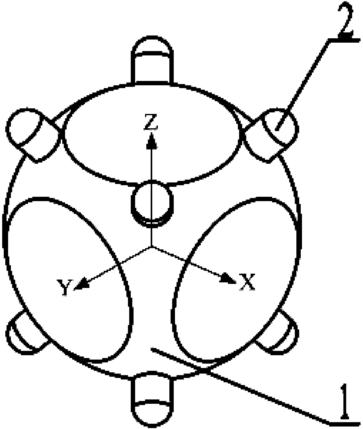
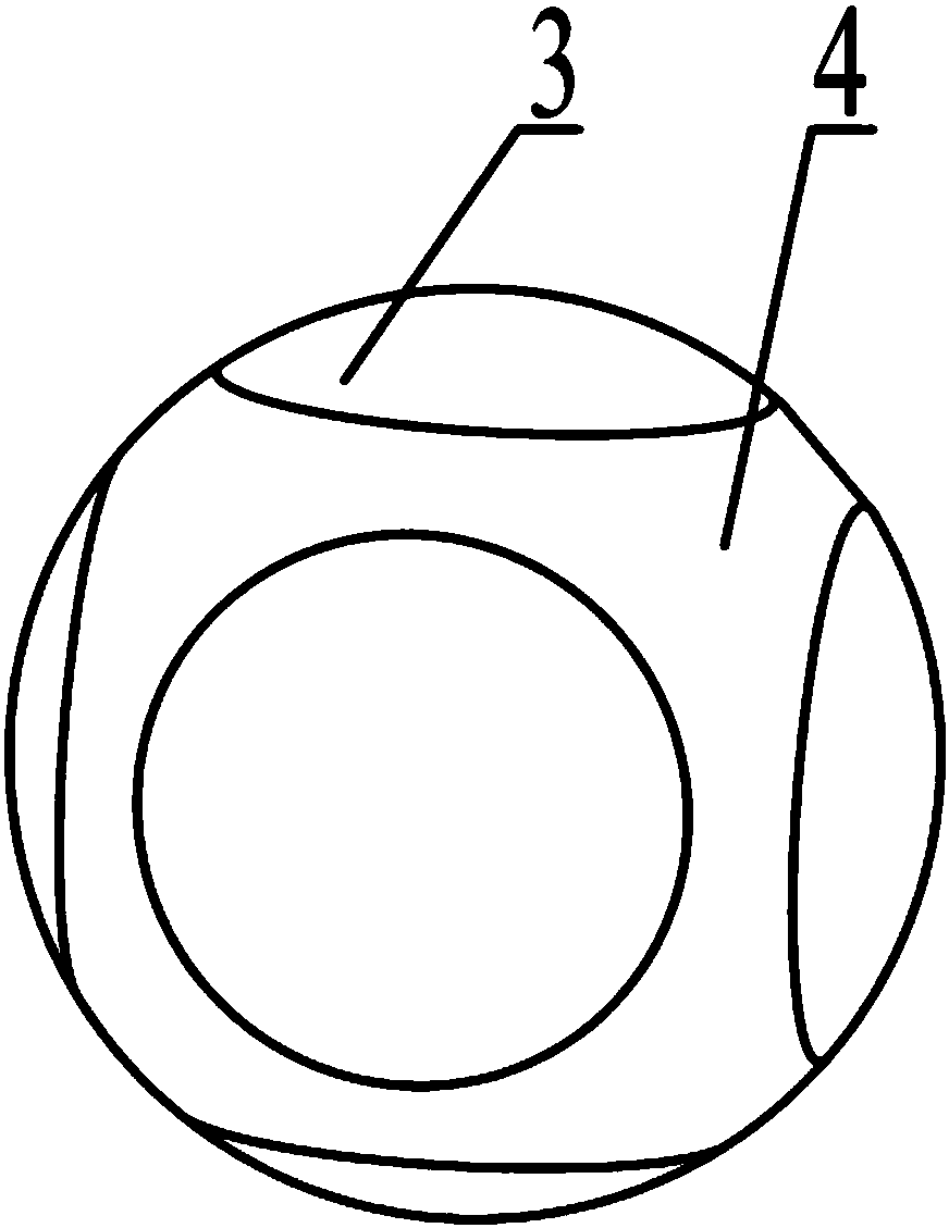
[0019] Specific implementation mode one: refer to Figure 1 to Figure 3 Describe this embodiment in detail, the three-degree-of-freedom spherical stator ultrasonic motor stator base described in this embodiment includes a piezoelectric ceramic spherical shell 1 and eight driving feet 2,
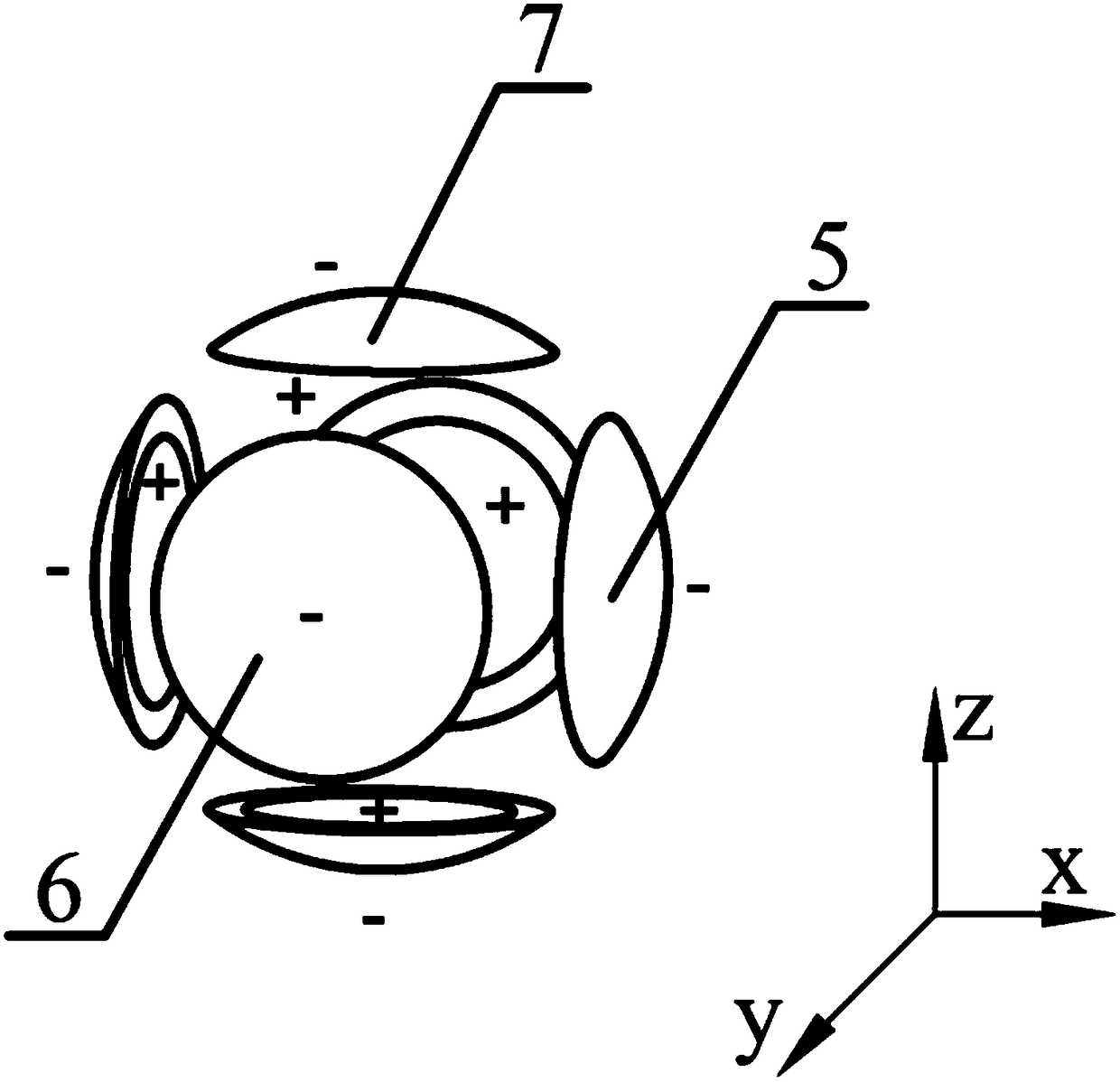
[0020] A pair of electrode partitions 5 in the direction of the x-axis, a pair of electrode partitions 6 in the direction of the y-axis, and a pair of z-axis direction of electrode partition 7,
[0021] The blank area between all the electrode partitions is the non-electrode area 4,
[0022] The polarization direction of each pair of electrode partitions is the same, and all electrode partitions are polarized along the thickness direction of the ball diameter,
[0023] The eight driving feet 2 are evenly arranged on the non-electrode area 4, and the spatial phase differences between the eight driving feet 2 and the electrode partition 5 in the x-axis direction, the electrode partition 6 in ...
specific Embodiment approach 2
[0026] Embodiment 2: The excitation method of the stator base of the three-degree-of-freedom spherical stator ultrasonic motor described in this embodiment is based on the three-degree-of-freedom spherical stator stator base of the ultrasonic motor described in Embodiment 1. The excitation method can Excite the three-degree-of-freedom spherical stator ultrasonic motor stator base to realize three-degree-of-freedom movement, and the three degrees of freedom include elliptical rotation around the x, y and z axes;
[0027] The excitation method of the three-degree-of-freedom spherical stator ultrasonic motor stator base driving the motor rotor to rotate around the x-axis:
[0028] A phase excitation voltage is applied to the electrode partition 6 in the y-axis direction and the electrode partition 7 in the z-axis direction, so that the piezoelectric ceramic spherical shell 1 produces a yaw-like vibration mode along the y-axis and z-axis directions, so that along the y-axis and z-a...
specific Embodiment approach 3
[0038] Specific implementation mode three: refer to Figure 4 Describe this embodiment in detail. This embodiment is to further explain the excitation method of the stator base of the three-degree-of-freedom spherical stator ultrasonic motor described in the second embodiment. In this embodiment, the electrode partitions 6 and z in the y-axis direction The excitation voltage with an amplitude of 60V is applied to the electrode partitions 7 in the axial direction, and the positive and negative poles of the anti-phase voltage with a phase amplitude of 60V are respectively connected to a pair of electrode partitions 6 in the y-axis direction, and the opposite phase voltage with an amplitude of 60V is respectively connected to a pair of electrode partitions 6 in the y-axis direction. The positive and negative poles of the phase voltage are respectively connected to a pair of electrode partitions 7 in the z-axis direction.
[0039] In this embodiment, if Figure 4 As shown, the po...
PUM
 Abstract
Description
Claims
Application Information
 - R&D
- Intellectual Property
- Life Sciences
- Materials
- Tech Scout
- Unparalleled Data Quality
- Higher Quality Content
- 60% Fewer Hallucinations
Browse by: Latest US Patents, China's latest patents, Technical Efficacy Thesaurus, Application Domain, Technology Topic, Popular Technical Reports.
© 2025 PatSnap. All rights reserved.Legal|Privacy policy|Modern Slavery Act Transparency Statement|Sitemap|About US| Contact US: help@patsnap.com


