Photomask occluding door and photomask storage apparatus

A technology for shielding doors and masks, applied in the arrangement of door leaves, windows/doors, and wing leaves, etc., can solve the problems of contaminating the mask, aging damage, affecting the yield of the mask, etc., so as to reduce the risk of deposition and reduce the effect of space

Active Publication Date: 2018-08-07
WUHAN CHINA STAR OPTOELECTRONICS TECH CO LTD
View PDF5 Cites 2 Cited by
  • Summary
  • Abstract
  • Description
  • Claims
  • Application Information

AI Technical Summary

Problems solved by technology

[0002] The photomask cabinet is a device used to store photomasks. The photomasks are arranged in multiple layers in the photomask cabinet. The existing photomask cabinet is open and bright on one side and is directly exposed to the surrounding environment. Long-term placement will cause dust particles to accumulate. On the surface of the photomask, the photomask will be dirty or even damaged due to aging. In addition, a large amount of dust particles will accumulate in the photomask cabinet, which will indirectly pollute the stored photomask.
[0003] The existing method to deal with dust particles is to add a cleaning process. However, there are dead corners in the photomask cabinet, which are difficult to clean, and the dust particles on the surface of the photomask are also very easy to scratch the photomask during the cleaning process, affecting the quality of the photomask. Yield

Method used


Image

  • Photomask occluding door and photomask storage apparatus
  • Photomask occluding door and photomask storage apparatus
  • Photomask occluding door and photomask storage apparatus

Examples


Embodiment Construction

[0033] The technical solutions in the embodiments of the present invention will be clearly and completely described below in conjunction with the accompanying drawings in the embodiments of the present invention. Obviously, the described embodiments are only part of the embodiments of the present invention, not all of them. Based on the implementation manners in the present invention, all other implementation manners obtained by persons of ordinary skill in the art without making creative efforts belong to the scope of protection of the present invention.

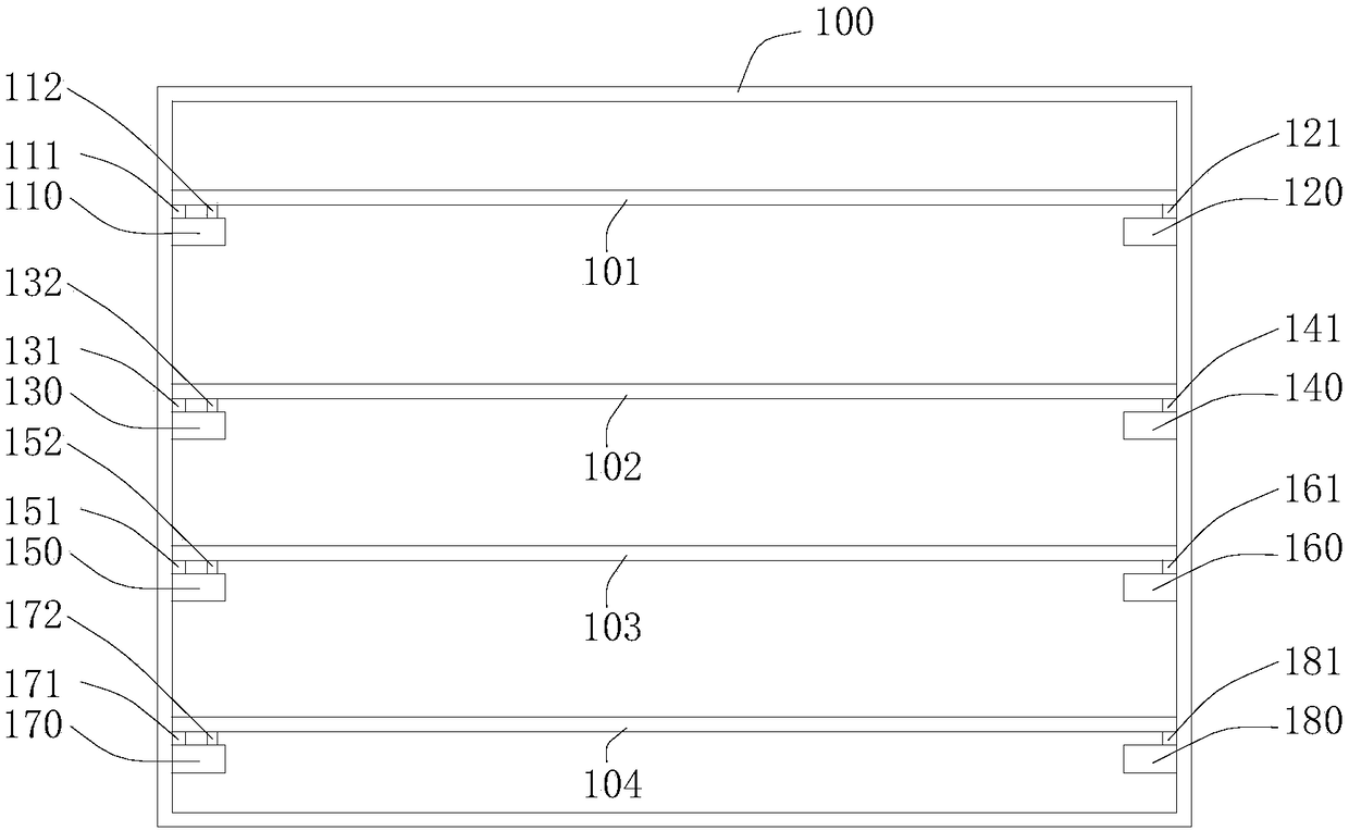
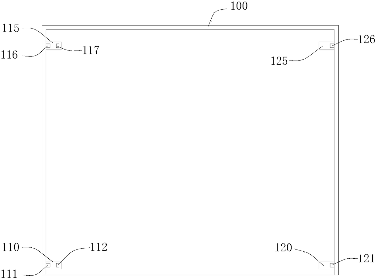
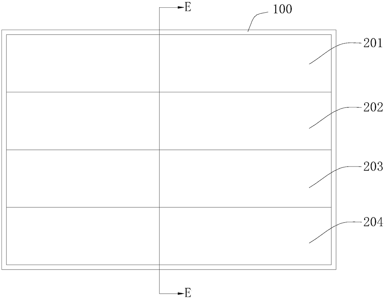
[0034] Please refer to figure 1 and figure 2 , figure 1 It is a schematic diagram of the front structure of a photomask cabinet in an embodiment, figure 2 Yes figure 1 The schematic diagram of the top view of the photomask cabinet, omitting the photomask. The photomask cabinet 100 includes inner walls of upper, lower, left, right and rear sides, and the front side is directly exposed to the surrounding environment. T...


PUM


Abstract

The invention provides a photomask occluding door, comprising a first occluding plate and a second occluding plate which are arranged on one side of an opening of a photomask cabinet and used for occluding storage positions of adjacent first and second photomasks in the photomask cabinet. A direction in which the first photomask is removed from the photomask cabinet is a first direction; in the first direction, the first occluding plate and the second occluding plate include areas at least partially overlapped; the first occluding plate and the second occluding plate are staggered on the lateral side of the opening of the photomask cabinet; the first occluding plate and the second occluding plate are in slidable connection; when accessing the first photomask is required, the first occluding plate is moved to the second occluding plate; when accessing the second photomask is required, the second occluding plate is moved to the first occluding plate. The photomask occluding door with theabove arrangements allows the first occluding plate or the second occluding plate to be partially opened, so that the photomask cabinet is exposed to surrounding space to less degree, and the risk for dust particulate matters to enter and deposit in the photomask cabinet is reduced. The invention also provides a photomask storage apparatus.

Description

technical field [0001] The invention belongs to the technical field of photomask storage, and in particular relates to a photomask shielding door and a photomask storage device. Background technique [0002] The photomask cabinet is a device used to store photomasks. The photomasks are arranged in multiple layers in the photomask cabinet. The existing photomask cabinet is open and bright on one side and is directly exposed to the surrounding environment. Long-term placement will cause dust particles to accumulate. On the surface of the photomask, the photomask is dirty or even damaged due to aging. In addition, a large amount of dust particles will accumulate in the photomask cabinet, which will indirectly pollute the stored photomask. [0003] The existing method to deal with dust particles is to add a cleaning process. However, there are dead corners in the photomask cabinet, which are difficult to clean, and the dust particles on the surface of the photomask are also very...

Claims


Application Information

Patent Timeline
IPC IPC(8): E06B5/00E06B3/46E06B3/70A47B81/00
Inventor 谌腾
Owner WUHAN CHINA STAR OPTOELECTRONICS TECH CO LTD
Why Eureka
Try Eureka